# C920 rework kit
# mk1 C920 rework video instructions
Reworking Logitech C920 camera is not difficult, but you should have right tools and some tinkering skills. After dissecting original camera, save 4 screws to reuse for securing PCB inside new case. For full instructions see video below.
# mk2 C920 rework video instructions
Reworking Logitech C920 camera is not difficult, but you should have right tools and some tinkering skills. For full instructions see video below.
# mk1 C920 PCBA wiring
#### New C920 wiring
Recently updated C920 webcam version was released featuring new PCB. These changes introduced two unexpected issues: wiring is different and new PCB has mechanical interference with [aluminium rework kit](https://www.kurokesu.com/shop/KITC920) back plate.
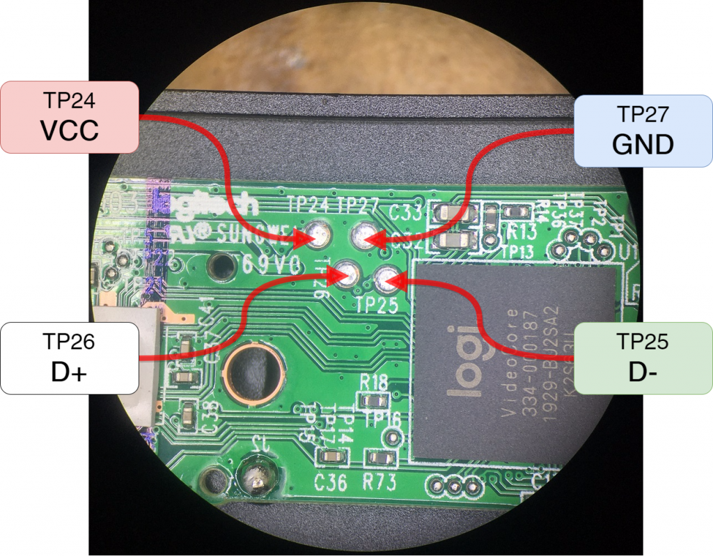
If you rework webcam by yourself, please use pin-out diagram as pictured below to solder wires.
[](https://wiki.kurokesu.com/uploads/images/gallery/2020-07/wiring_out-1024x799.png)
| **Test point** | **Signal** |
| TP24 | VCC |
| TP26 | USB D+ |
| TP25 | USB D- |
| TP27 | GND |
[](https://wiki.kurokesu.com/uploads/images/gallery/2020-07/wiring-1024x361.jpg)
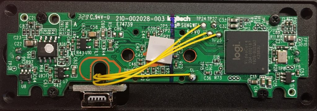
Interesting note - looks like new PCB release was rushed, spot mirrored J2 designator.
Original [blog post](https://www.kurokesu.com/main/2019/12/22/c920-rework-kit-updates/) about changes
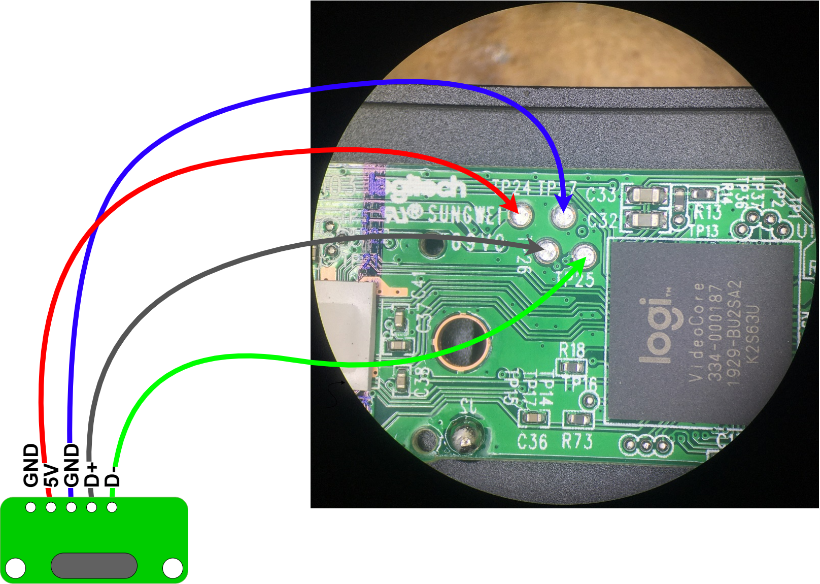
#### Old C920 wiring
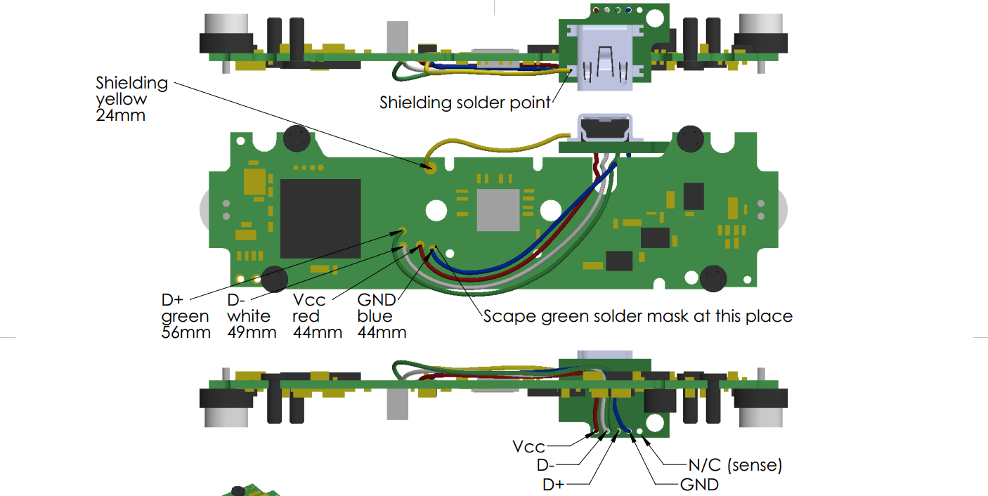
Route USB wires as indicated in this diagram. I found Kynar monolithic wires are the best – small and easy to solder. 5 wires will be used USB D+, D-, GND, Power. Shield also has to be soldered.
[](https://wiki.kurokesu.com/uploads/images/gallery/2020-07/4.png)
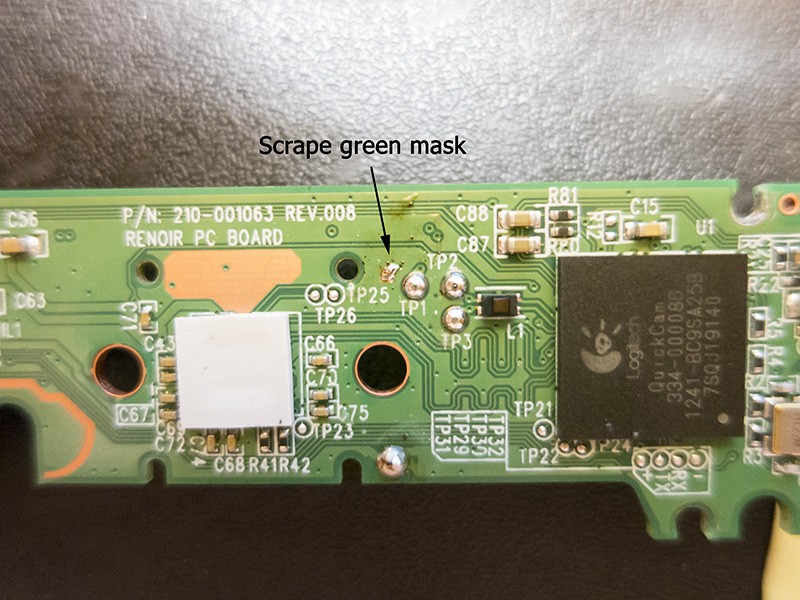
USB connector is available on the other side of PCB and it is surface mount type. Therefore it will be easier to use test pins. While GND is not available as test pin I recommend making pad by yourself. You can also use other places to solder GND wire, it is just my recommendation. Scrape green soldering mask with scalpel to access GND.
[](https://wiki.kurokesu.com/uploads/images/gallery/2020-07/1.jpg)# mk2 C920 PCBA wiring
Camera kit has internal USB-C type connector also back plate has features to use [USB-C cable with lock screws](https://www.kurokesu.com/shop/CABLE_USB_USBC_1.5M_LOCK).
#### Prepare USB adapter
Cut and strip included Kynar wire in 4 pieces.
[](https://wiki.kurokesu.com/uploads/images/gallery/2021-05/wires.jpg)
Solder prepared wires to USB-C adapter (please note do not solder a wire to the left most reserved pad on USB-C adapter)
[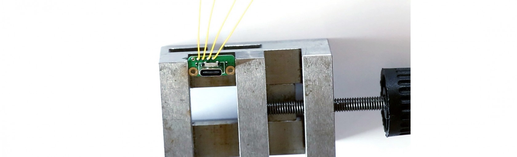](https://wiki.kurokesu.com/uploads/images/gallery/2021-05/solder2.jpg)
#### C920 PCBA to USB adapter wiring
There are at least two C920 board major versions with different test point layouts. Identify your board and solder wires accordingly.
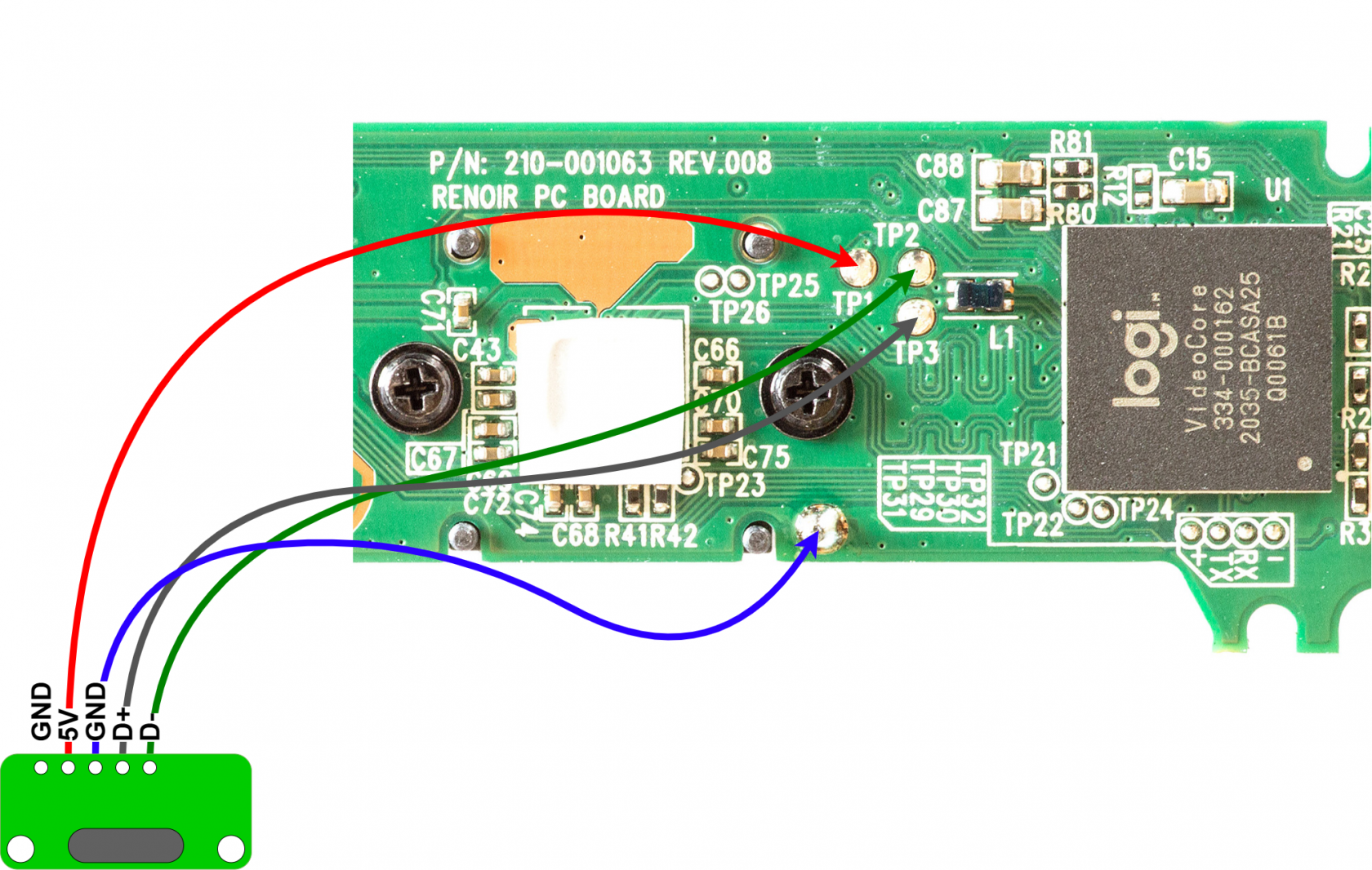
##### New C920 board wiring
While component placement is different, same Test Pin (TP) arrangement is valid for **C930e** cameras.
[](https://wiki.kurokesu.com/uploads/images/gallery/2021-05/wiring_new.png)
#####
##### Old C920 board wiring
[](https://wiki.kurokesu.com/uploads/images/gallery/2021-06/wiring_old3.png)# Mounting a filter
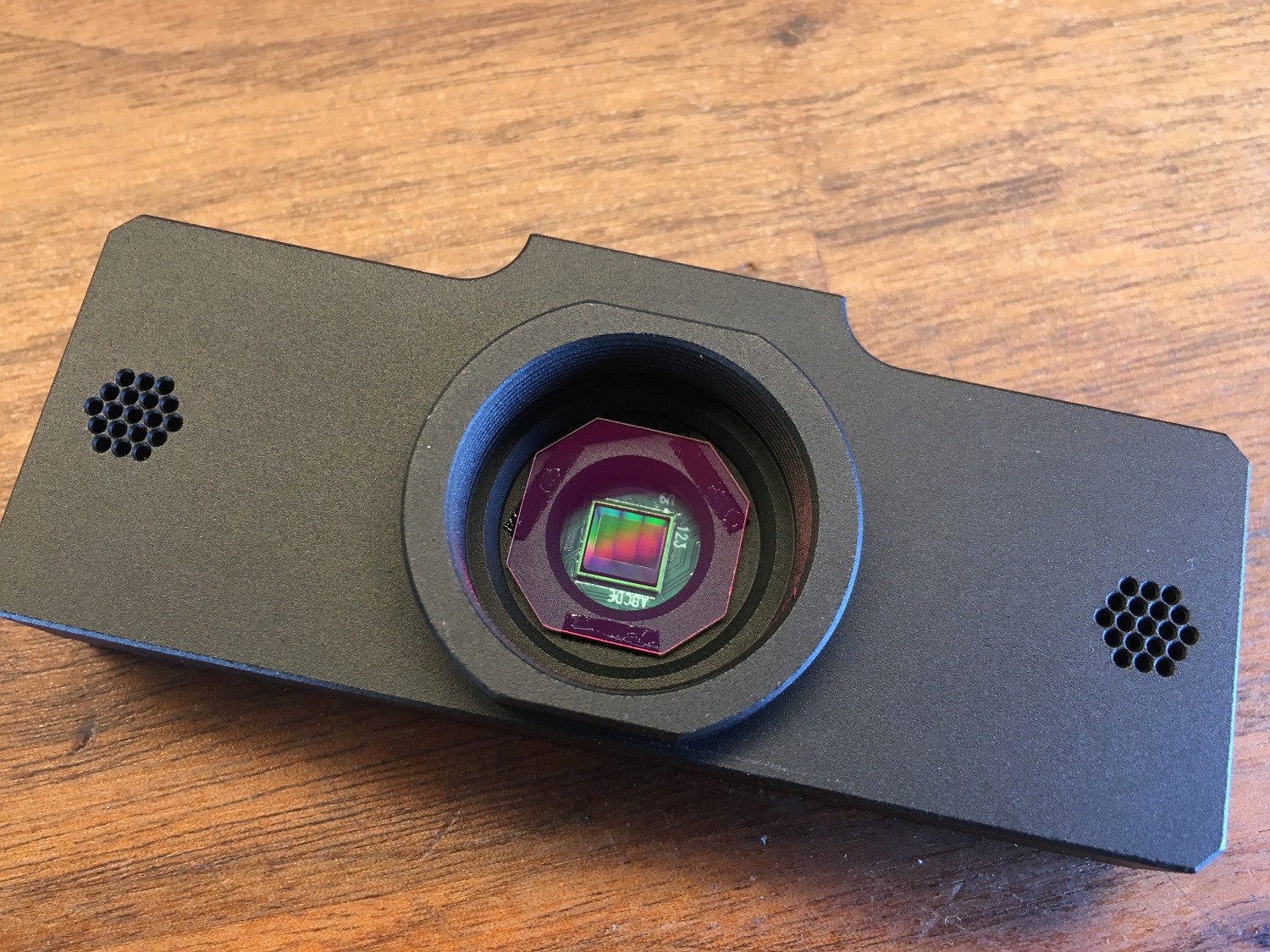
Logitech C920 comes with IR low pass filter installed. Without this filter camera becomes sensitive to Infrared light. In order to maintain the same functionality you should install filter with same [specifications](http://www.kurokesu.com/shop/F2LOW650). If you wish to use camera for night vision purposes, leave it as is – don’t install any filter. In some other cases you might want to see only Infrared light. In this case install [another filter](http://www.kurokesu.com/shop/F2HIGH850). To install filter stick few strips of double sided adhesive tape and drop filter inside.
[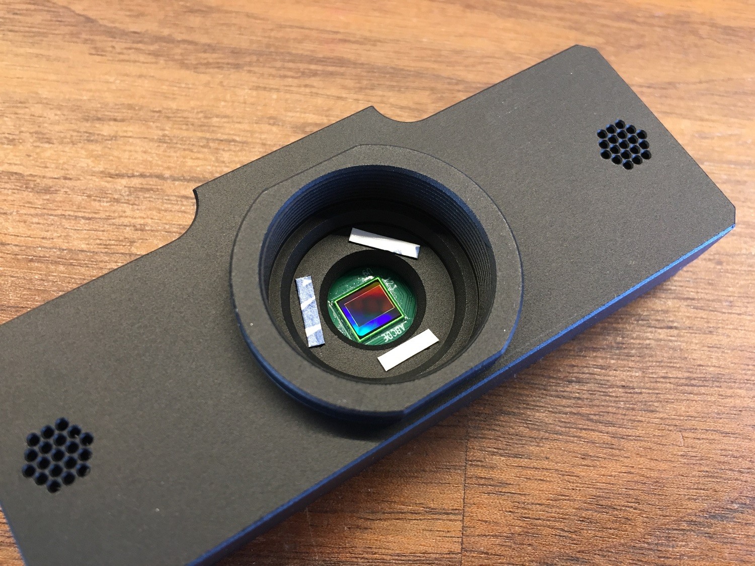](https://wiki.kurokesu.com/uploads/images/gallery/2020-07/1r.jpg)
[](https://wiki.kurokesu.com/uploads/images/gallery/2020-07/2r.jpg)# mk1 dimensions and kit parts
C920 rework kit dimensions comes as a kit. Main parts are 2 aluminum parts, when assembled dimensions are 88\*37\*18.9mm. Kit also includes allen 2x keys and 5 DIN 912 screws (1x M2x5, 4xM2.5×6). USB board with soldered connector also included.
[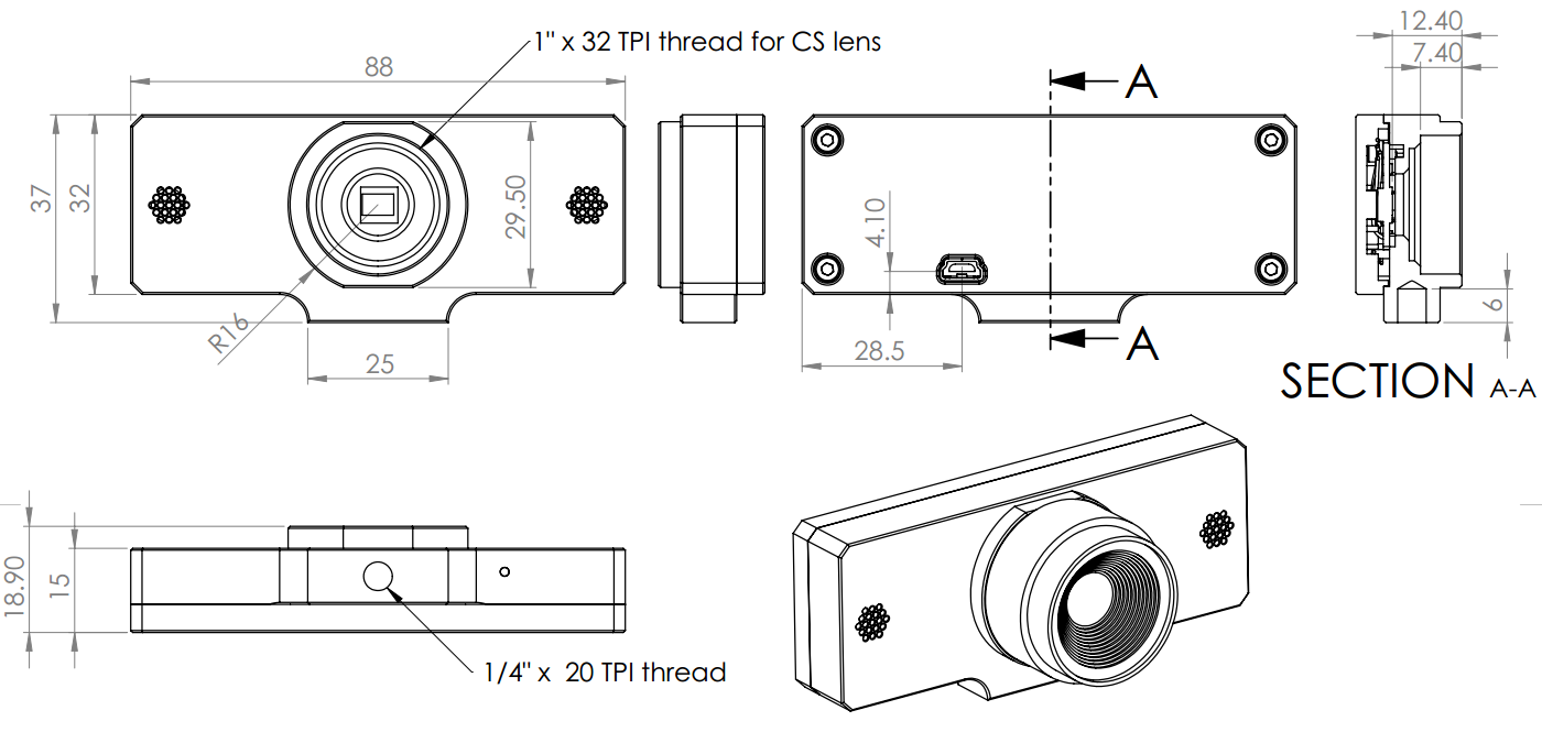](https://wiki.kurokesu.com/uploads/images/gallery/2020-07/dimensions.png)
#### Exploded view
[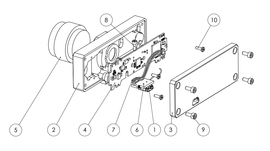](https://wiki.kurokesu.com/uploads/images/gallery/2020-07/1.png)
| **Item nr** | **Part** | **Description** | **Qty** |
| 1 | USB mini socket | | 1 |
| 2 | LP0144-P0001 | | 1 |
| 3 | LP0144-P0002 | | 1 |
| 4 | | PCBA extracted from C920 camera | 1 |
| 5 | | Lens | 1 |
| 6 | USB mini PCB assembly | | 1 |
| 7 | | Wires | 1 |
| 8 | DIN912 M2x5 | | 1 |
| 9 | DIN912 M2.5x6 | | 4 |
| 10 | | Camera screws | 4 |
#### 3D model
3D model is uploaded to [**github repository**](https://github.com/Kurokesu/3d_models)# mk2 dimensions and kit parts
C920 rework kit dimensions comes as a kit. Main parts are 2 aluminum parts, when assembled dimensions are 88\*32\*18.9mm.
[](https://wiki.kurokesu.com/uploads/images/gallery/2021-05/LP0144_mk2_dimensions.png)
#### Exploded view
[](https://wiki.kurokesu.com/uploads/images/gallery/2021-05/LP0144_mk2_exploded_2.png)
| **Item nr** | **Part** | **Description** | **Qty** |
| 1 | LP0144-P0002C | Back plate | 1 |
| 2 | LP0144-P0011C | Front plate | 1 |
| 3 | DIN912 M1.6 x 5
| Screws to mount C920 PCBA | 4 |
| 4 | DIN912 M2.5 x 8
| | 4 |
| 5 | | C920 PCBA | 1 |
| 7 | | USB-C cable
| 1 |
| 9 | DIN912 M2 x 4
| Screws to mount USB-C adapter | 2 |
| 10 | DIN912 M3 x 5
| Screws to mount tripod plate | 2 |
| 11 | QR\_PLATE\_20 | Tripod and Arca-Swiss mount plate | 1 |
| 12 | | Dust cap | 1 |
| 13 | | USB-C adapter board | 1 |
# mk1 vs mk2
| **Feature** | **mk1** | **mk2** |
| Filter mount | adhesive tape (top)
| adhesive tape (top or bot) |
| USB Cable lock screws | No
| Yes |
| Soldering required | Yes
| Yes |
| Design | Initial
| Partial redesign
|
| Swiss-Arca mount | No
| Optional (top/bot)
|
| Mount | ¼” 20TPI (bot)
| 4x M3 (top/bot more flexible design)
|
| PCB mount | Salvaged self tapping scres
| M1.6 screws (easier to mount)
|
| Integrated tripod mount | Yes
| No
|
| USB pcb mount | Sideways
| Straight
|
# C920 vs C930
Recently Logitech ditched h.264 support for most of their cameras. Original C920 has only MJPEG and YUYV compression. If you need on board h.264 codec, please use C930 camera.