# IMX477_Z1_LEGACY

# Overview

<span class="fontstyle0">Kurokesu IMX477 image sensor (1/2.3", 12.3MP) board with MIPI CSI-2 interface is designed to match motorized zoom lenses.   
</span>

<span class="fontstyle0">[![IMG_7076__s3.jpg](https://wiki.kurokesu.com/uploads/images/gallery/2022-05/scaled-1680-/img-7076-s3.jpg)](https://wiki.kurokesu.com/uploads/images/gallery/2022-05/img-7076-s3.jpg)</span># Features

- Sensor: IMX477
- Optical Format: 1/2.3″ (diagonal 7.857mm)
- Resolution: 4056(H) x 3040(V) 12.3MP
- Pixel Size: 1.55μm x 1.55μm
- Lane MIPI CSI-2
- Lens Mount: Board mount
- Multiple mounting options (designed to match [motorized zoom lenses](https://wiki.kurokesu.com/books/motorized-zoom-lenses))
- 4 lanes routed to FFC connector# Specifications

<table border="1" id="bkmrk-pixels-1920h-x-1080v" style="border-collapse: collapse; width: 100%;"><tbody><tr><td style="width: 50%;">Pixels</td><td style="width: 50%;">4056 H x 3040 V</td></tr><tr><td style="width: 50%;">Sensor size</td><td style="width: 50%;">7.564 x 5.476 mm</td></tr><tr><td style="width: 50%;">Shutter</td><td style="width: 50%;">Electronic Rolling Shutter</td></tr><tr><td style="width: 50%;">Sensor pixel size</td><td style="width: 50%;">1.5μm x 1.5μm</td></tr><tr><td style="width: 50%;">Scan</td><td style="width: 50%;">Progressive</td></tr><tr><td style="width: 50%;">Rated power</td><td style="width: 50%;">2W max

</td></tr><tr><td style="width: 50%;">Sensor</td><td style="width: 50%;">Sony IMX477-AACK</td></tr><tr><td style="width: 50%;">Weight</td><td style="width: 50%;">4g</td></tr><tr><td style="width: 50%;">Lens mount</td><td style="width: 50%;">Board mount</td></tr><tr><td style="width: 50%;">Operational temperature</td><td style="width: 50%;">TBD</td></tr><tr><td style="width: 50%;">Weight</td><td style="width: 50%;">30.5×37×4.17mm</td></tr></tbody></table># FFC connector pin-out

IMX477 camera board has 22pin 0.5mm spaced pitch FFC connector 687122183722 from [Würth Elektronik](https://www.we-online.com/catalog/en/FPC_0_5_SMT_ZIF_HORIZONTAL_BOTTOM_CONTACT_LOW_PROFILE_6871XX183722). Cable orientation is bottom (see notes on the PCB).

[![IMG_7080__s2.jpg](https://wiki.kurokesu.com/uploads/images/gallery/2022-05/scaled-1680-/img-7080-s2.jpg)](https://wiki.kurokesu.com/uploads/images/gallery/2022-05/img-7080-s2.jpg)

#### Pinout table

<table border="1" id="bkmrk-pin-nr-signal-note-1" style="border-collapse: collapse; width: 100%; height: 667px;"><tbody><tr style="height: 29px;"><td class="align-center" style="width: 11.6049%; height: 29px;">**Pin nr**</td><td class="align-center" style="width: 34.1975%; height: 29px;">**Signal**</td><td class="align-center" style="width: 54.1975%; height: 29px;">**Note**</td></tr><tr style="height: 29px;"><td style="width: 11.6049%; height: 29px;">1</td><td style="width: 34.1975%; height: 29px;">GND</td><td style="width: 54.1975%; height: 29px;"> </td></tr><tr style="height: 29px;"><td style="width: 11.6049%; height: 29px;">2</td><td style="width: 34.1975%; height: 29px;">MIPI\_D1\_N</td><td style="width: 54.1975%; height: 29px;"> </td></tr><tr style="height: 29px;"><td style="width: 11.6049%; height: 29px;">3</td><td style="width: 34.1975%; height: 29px;">MIPI\_D1\_P</td><td style="width: 54.1975%; height: 29px;"> </td></tr><tr style="height: 29px;"><td style="width: 11.6049%; height: 29px;">4</td><td style="width: 34.1975%; height: 29px;">GND</td><td style="width: 54.1975%; height: 29px;"> </td></tr><tr style="height: 29px;"><td style="width: 11.6049%; height: 29px;">5</td><td style="width: 34.1975%; height: 29px;">MIPI\_D2\_N</td><td style="width: 54.1975%; height: 29px;"> </td></tr><tr style="height: 29px;"><td style="width: 11.6049%; height: 29px;">6</td><td style="width: 34.1975%; height: 29px;">MIPI\_D2\_P</td><td style="width: 54.1975%; height: 29px;"> </td></tr><tr style="height: 29px;"><td style="width: 11.6049%; height: 29px;">7</td><td style="width: 34.1975%; height: 29px;">GND</td><td style="width: 54.1975%; height: 29px;"> </td></tr><tr style="height: 29px;"><td style="width: 11.6049%; height: 29px;">8</td><td style="width: 34.1975%; height: 29px;">MIPI\_CLK\_N</td><td style="width: 54.1975%; height: 29px;"> </td></tr><tr style="height: 29px;"><td style="width: 11.6049%; height: 29px;">9</td><td style="width: 34.1975%; height: 29px;">MIPI\_CLK\_P</td><td style="width: 54.1975%; height: 29px;"> </td></tr><tr style="height: 29px;"><td style="width: 11.6049%; height: 29px;">10</td><td style="width: 34.1975%; height: 29px;">GND</td><td style="width: 54.1975%; height: 29px;"> </td></tr><tr style="height: 29px;"><td style="width: 11.6049%; height: 29px;">11</td><td style="width: 34.1975%; height: 29px;">MIPI\_D3\_N</td><td style="width: 54.1975%; height: 29px;"> </td></tr><tr style="height: 29px;"><td style="width: 11.6049%; height: 29px;">12</td><td style="width: 34.1975%; height: 29px;">MIPI\_D3\_P</td><td style="width: 54.1975%; height: 29px;"> </td></tr><tr style="height: 29px;"><td style="width: 11.6049%; height: 29px;">13</td><td style="width: 34.1975%; height: 29px;">GND</td><td style="width: 54.1975%; height: 29px;"> </td></tr><tr style="height: 29px;"><td style="width: 11.6049%; height: 29px;">14</td><td style="width: 34.1975%; height: 29px;">MIPI\_D4\_N</td><td style="width: 54.1975%; height: 29px;"> </td></tr><tr style="height: 29px;"><td style="width: 11.6049%; height: 29px;">15</td><td style="width: 34.1975%; height: 29px;">MIPI\_D4\_P</td><td style="width: 54.1975%; height: 29px;"> </td></tr><tr style="height: 29px;"><td style="width: 11.6049%; height: 29px;">16</td><td style="width: 34.1975%; height: 29px;">GND</td><td style="width: 54.1975%; height: 29px;"> </td></tr><tr style="height: 29px;"><td style="width: 11.6049%; height: 29px;">17</td><td style="width: 34.1975%; height: 29px;">SEN\_PWR\_2.8V</td><td style="width: 54.1975%; height: 29px;">Sensor analog power supply</td></tr><tr style="height: 29px;"><td style="width: 11.6049%; height: 29px;">18</td><td style="width: 34.1975%; height: 29px;">LED</td><td style="width: 54.1975%; height: 29px;">Not used</td></tr><tr style="height: 29px;"><td style="width: 11.6049%; height: 29px;">19</td><td style="width: 34.1975%; height: 29px;">GND</td><td style="width: 54.1975%; height: 29px;"> </td></tr><tr style="height: 29px;"><td style="width: 11.6049%; height: 29px;">20</td><td style="width: 34.1975%; height: 29px;">SCL</td><td style="width: 54.1975%; height: 29px;"> </td></tr><tr style="height: 29px;"><td style="width: 11.6049%; height: 29px;">21</td><td style="width: 34.1975%; height: 29px;">SDA</td><td style="width: 54.1975%; height: 29px;"> </td></tr><tr style="height: 29px;"><td style="width: 11.6049%; height: 29px;">22</td><td style="width: 34.1975%; height: 29px;">3.3V</td><td style="width: 54.1975%; height: 29px;">Logic power supply</td></tr></tbody></table>

#### Connectivity with Raspberry PI compute module

Use 22pin 0.5mm pitch FFC cable like 687622050002 (5cm) / 687622100002 (10cm) from [Würth Elektronik](https://www.we-online.com/catalog/en/FFC_0_50_TYPE_1_6876XXXXX002)

[![IMG_7091__s2.jpg](https://wiki.kurokesu.com/uploads/images/gallery/2022-05/scaled-1680-/img-7091-s2.jpg)](https://wiki.kurokesu.com/uploads/images/gallery/2022-05/img-7091-s2.jpg)

#### TOP / BOT connector

Initially, we designed an IMX477 board to be used with Raspberry Pi CM4 IO board and selected 22pin 0.5mm pitch connector contacts facing BOTTOM. It was a direct connection from IMX477 to the CM4 IO board with non reversed FFC cable.  
We have replaced the connector facing the TOP side to be more flexible. It allows the same connection to CM4 IO board with reversed FFC cable. Also, standard 22pin 0.5mm to 15pin 1.0mm cables can be used to attach to more boards like NVIDIA Jetson, or other modifications of the Raspberry Pi compute modules.

[![IMG_7909_r.jpg](https://wiki.kurokesu.com/uploads/images/gallery/2023-02/scaled-1680-/img-7909-r.jpg)](https://wiki.kurokesu.com/uploads/images/gallery/2023-02/img-7909-r.jpg)# Dimensions

[![LP0687_IMX477_Z1_LEGACY_2.PNG](https://wiki.kurokesu.com/uploads/images/gallery/2022-05/scaled-1680-/lp0687-imx477-z1-legacy-2.PNG)](https://wiki.kurokesu.com/uploads/images/gallery/2022-05/lp0687-imx477-z1-legacy-2.PNG)

<p class="callout info">3D model is maintained in our [official GitHub repository](https://github.com/Kurokesu/3d_models)</p># Using with Raspberry Pi

#### Raspberry Pi CM4 compute module

Quick guide how to use camera module with [Raspberry Pi compute module](https://www.raspberrypi.com/products/compute-module-4/?variant=raspberry-pi-cm4001000) and [IO board](https://www.raspberrypi.com/products/compute-module-4-io-board/). Raspberry Pi software is in active development thus changes fairly quickly. We will touch preparation procedure very briefly.

<p class="callout warning">Only compute modules support cameras without crypto chip.</p>

##### Prepare board

- Fit jumpers J2 - disable EMMC boot
- Fit jumpers J6 - enable CAM0, DISP0
- Connect camera co CAM1 port

[![IMG_7091__s2.jpg](https://wiki.kurokesu.com/uploads/images/gallery/2022-05/scaled-1680-/img-7091-s2.jpg)
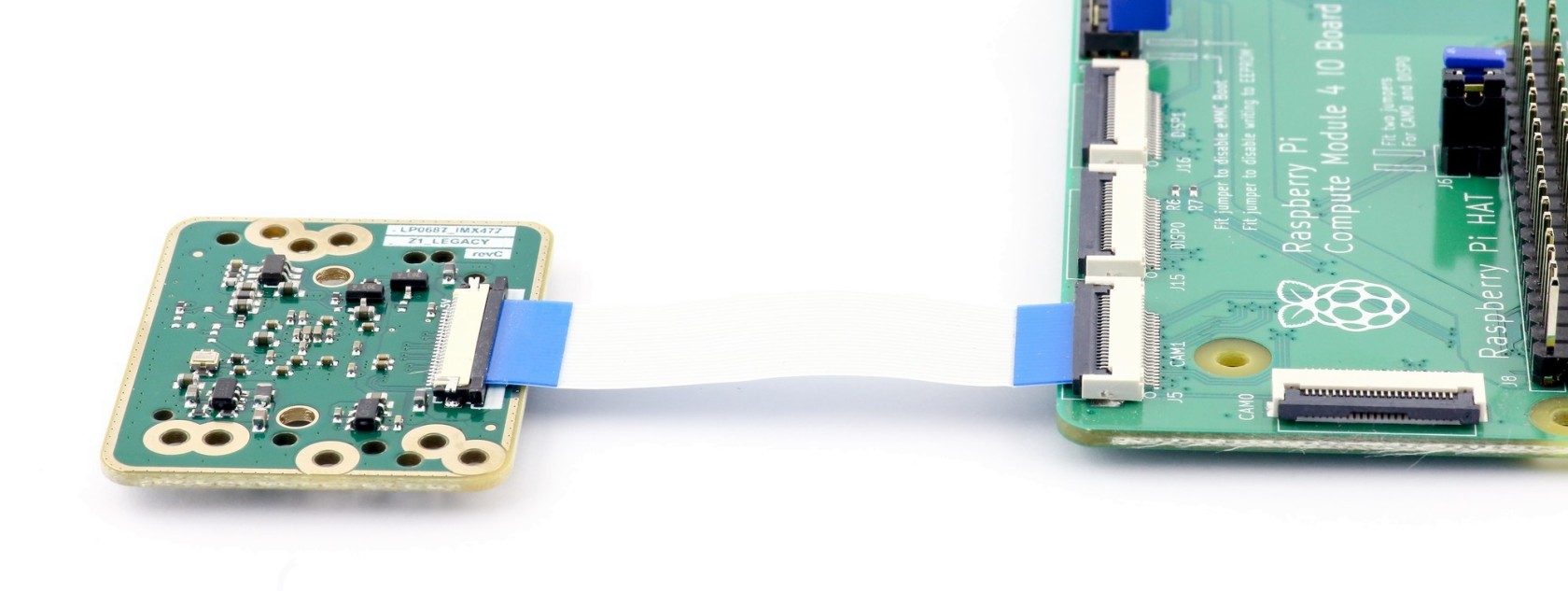
](https://wiki.kurokesu.com/uploads/images/gallery/2022-05/img-7091-s2.jpg)

##### Install OS

- Install rpiboot
- Start rpiboot
- Use rpi-imager to flash OS

##### Boot

- Remove J2 jumper - disable EMMC boot
- Scan for IP on local network
- Connect monitor and keyboard, finish setup
- Expand system

##### Prepare camera

- Setup single camera mode

```shell
sudo wget https://datasheets.raspberrypi.org/cmio/dt-blob-cam1.bin -O /boot/dt-blob.bin
sudo reboot
```

- Check if camera is detected after reboot

```shell
vcgencmd get_camera
```

##### Recipe #1 - show video in console as ASCII text

```shell
raspivid -t 0 -o - | gst-launch-1.0 fdsrc ! h264parse ! rtph264pay config-interval=1 pt=96 ! decodebin ! videoconvert ! aasink
```

##### Recipe #2 - stream video over network

- Start streaming on Raspberry Pi

```shell
raspivid -o - -t 9999999 |cvlc -vvv stream:///dev/stdin --sout '#rtp{sdp=rtsp://:8554/}' :demux=h264
```

- Start client on Windows computer (change Raspberry Pi IP address to match your setup)

```shell
set PATH=C:\gstreamer\1.0_1.18.3\bin\;C:\gstreamer\1.0_1.18.3\lib\gstreamer-1.0\;C:\gstreamer\1.0_1.18.4\libexec\gstreamer-1.0\
gst-launch-1.0 rtspsrc location=rtsp://192.168.0.86:8554/ latency=10 ! decodebin ! timeoverlay ! videoscale ! videoscale ! video/x-raw,width=1280,height=720 ! autovideosink
```

##### Demo video with 40x motorized zoom lens

For more details check [blog post](https://www.kurokesu.com/main/2022/01/24/imx477-camera-board-for-motorized-zoom-lenses/)

[![40x_optical_zoom_demo_2.jpg](https://wiki.kurokesu.com/uploads/images/gallery/2022-05/scaled-1680-/40x-optical-zoom-demo-2.jpg)
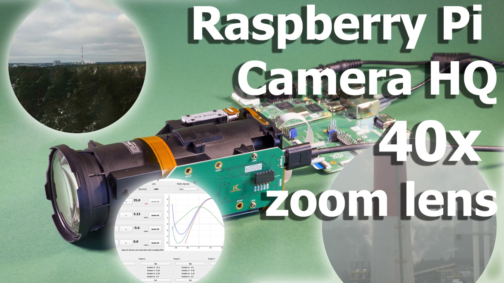
](https://wiki.kurokesu.com/uploads/images/gallery/2022-05/40x-optical-zoom-demo-2.jpg)# PCB revisions

#### RevA

- Proof of concept

#### RevB

- Route 4 MIPI lines
- Add lens holes

#### RevC

- Cleanup design
- Replace LDO with ones that can be purchased