# SCE2
# Overview
**SCE2-M** is a fully integrated stepper motor controller module for digital control for limited space applications. Designed for small 3D printers, laser cutters/engravers, CNC mills, pick and place machines, robots, test fixtures, and other motorized devices. SCE2-M module is the smallest motor controller that requires no external components and runs industry-standard g-code processor with linear interpolation control open-source firmware
[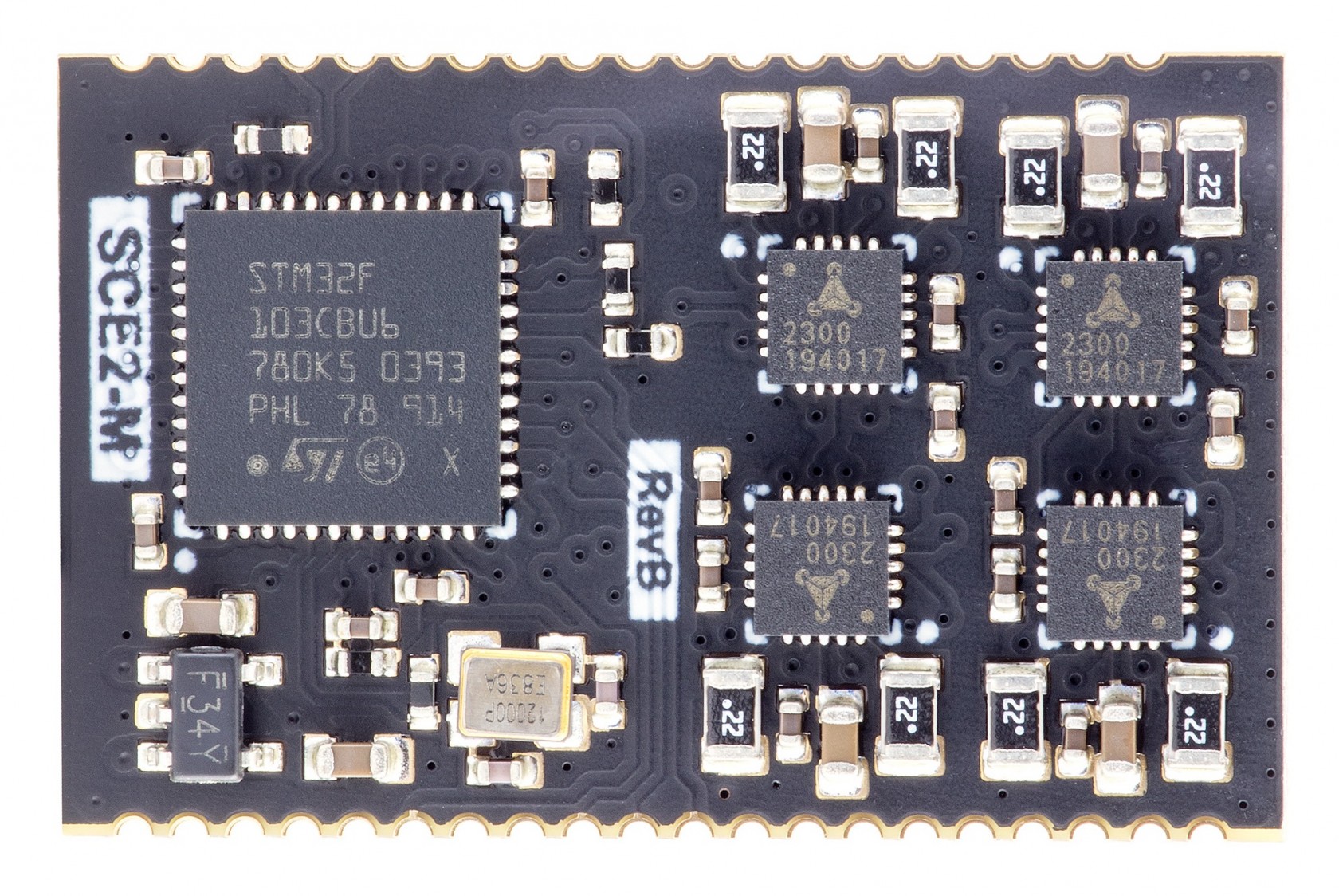](https://wiki.kurokesu.com/uploads/images/gallery/2021-02/IMG_2828_r_rot.jpg)# Features
- System On Module (SOM) design
- Fully integrated, ready to use
- 4 stepper motors drivers, up to 1/256 microstepping
- 4 Limit switch inputs
- Direct connect USB port
- Optional TTL USART/I2C ports 8 IO ports (some with hardware PWM output capability)
- 32bits ARM-Cortex M3 microcontroller, running at 72Mhz
- Advanced motor control with Trinamic drivers
- Digital current control of stepper motor drivers directly from g-code# Pinout
SCE2-M module has some STM32 pins routed to external pads. Pads grouped by functionality provided in tables below.
##### Pinout
[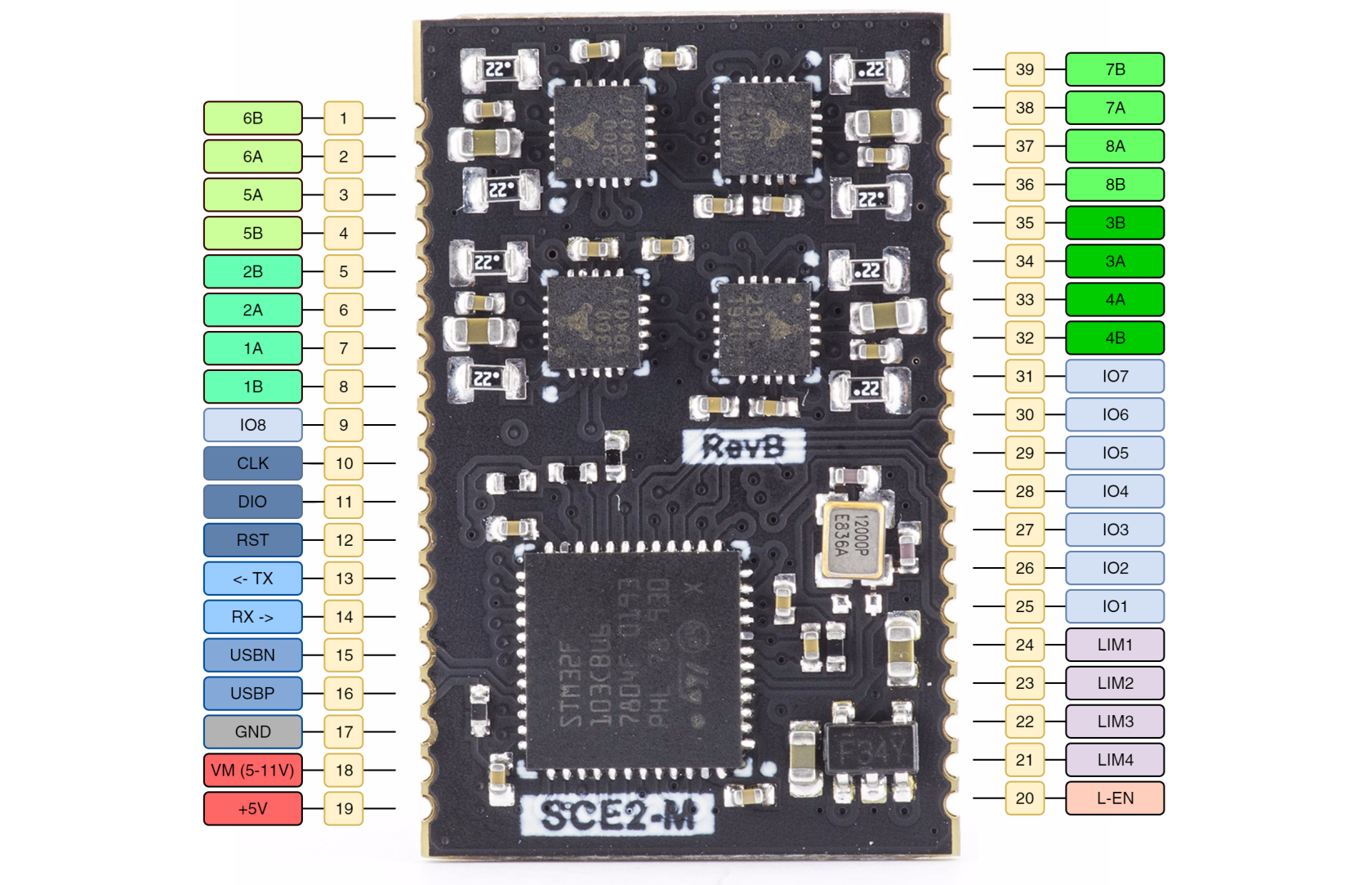](https://wiki.kurokesu.com/uploads/images/gallery/2021-10/sce2-m-diagram-w1.png)
##### GPIO pin mapping table
| **IO pin** | **CPU port** | **Function** | **CPU features** |
| 1 | PB1 | SPINDLE ENABLE | ADC |
| 2 | PB9 | PROBE | I2C SDA |
| 3 | PA8 | PWM OUTPUT | |
| 4 | PB4 | FLOOD | |
| 5 | PB3 | MIST | |
| 6 | PB0 | SPINDLE DIR | ADC |
| 7 | PB5 | STOP | |
| 8 | PB8 | | I2C SCL |
**PA8 (PWM OUTPUT)** is set to 10kHz frequency, but can be adjusted in firmware.
##### Limit switch mapping table
| **Port** | **Net name** |
| PB12 | LIMIT1 |
| PB13 | LIMIT2 |
| PB14 | LIMIT3 |
| PB15 | LIMIT4 |
| PA9 | LIMIT\_EN |
##### UART pin mapping table
| **CPU port** | **Net name** |
| PB7 | USART1\_RX |
| PB6 | USART1\_TX |
##### Schematic symbol
[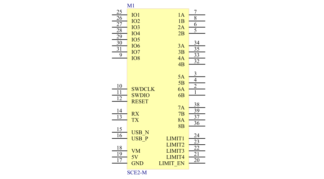](https://wiki.kurokesu.com/uploads/images/gallery/2021-10/sce2-m3.png)
5V is used for motor drivers. Logic level of all GPIO pins is 3.3V
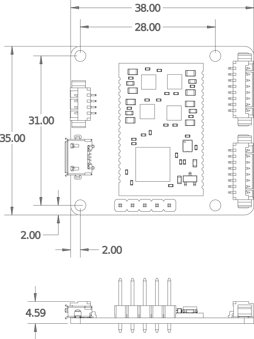
# Dimensions and footprint
#### Mechanical dimensions
#### [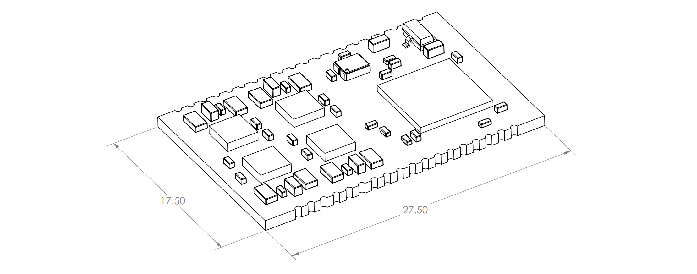](https://wiki.kurokesu.com/uploads/images/gallery/2021-10/sce2-m-2-dim1.png)
#### Component footprint
[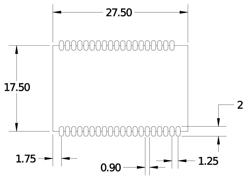](https://wiki.kurokesu.com/uploads/images/gallery/2020-09/sce2-m_footprint.png)
3D STEP file is maintained on [Github](https://github.com/Kurokesu/3d_models)
# Firmware
#### Connectivity
Firmware update can be done over SWD interface with an inexpensive programmer.
1\. If possible disconnect the lens from the controller.
2\. Connect programmer to the controller.
| **ST-LINK/V2 signal (pin)** | **Controller signal** |
| VAPP (1,2) | VAPP (3.3-5V) |
| GND (20) | GND |
| TRST (3) | RST |
| TMS\_SWDIO (7) | IO |
| TCK\_SWCLK (9) | CLK |
3\. Connect power supply to the controller.
[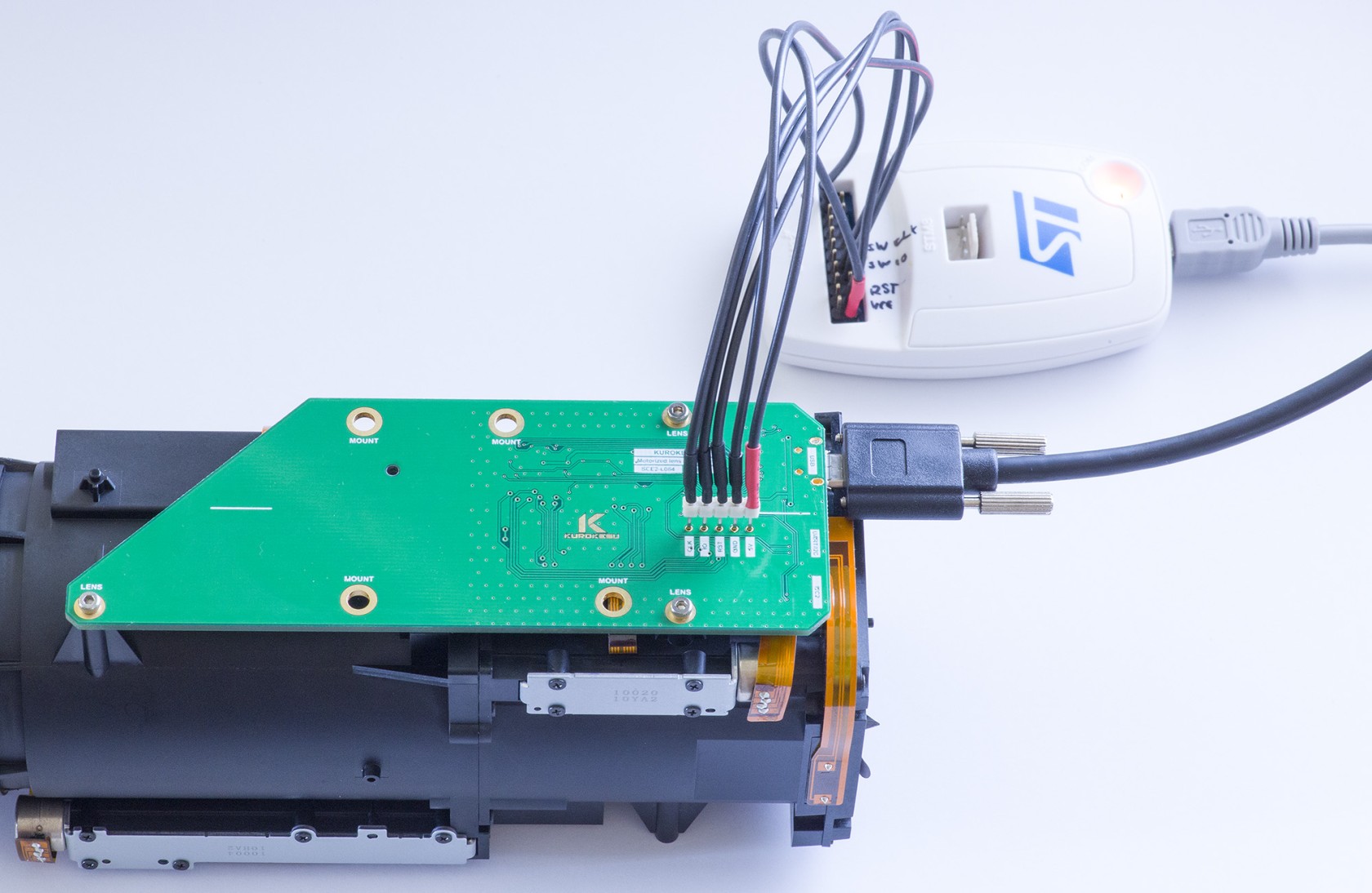](https://wiki.kurokesu.com/uploads/images/gallery/2022-08/img-7221-r.jpg)
#### Firmware update
Before updating firmware, read GRBL parameters! Use [tools](https://github.com/Kurokesu/SCE2-SDK/tree/main/01_send_parameters) to automate the process.
We recommend using original [ST-LINK/V2](https://www.st.com/en/development-tools/st-link-v2.html), [STLINK-V3SET](https://www.st.com/en/development-tools/stlink-v3set.html) or [STLINK-V3MINI](https://www.st.com/en/development-tools/stlink-v3mini.html) programmer. Download [STLINK-UTILITY](https://www.st.com/en/development-tools/stsw-link004.html) software from ST, open firmware file and program the microcontroller.
[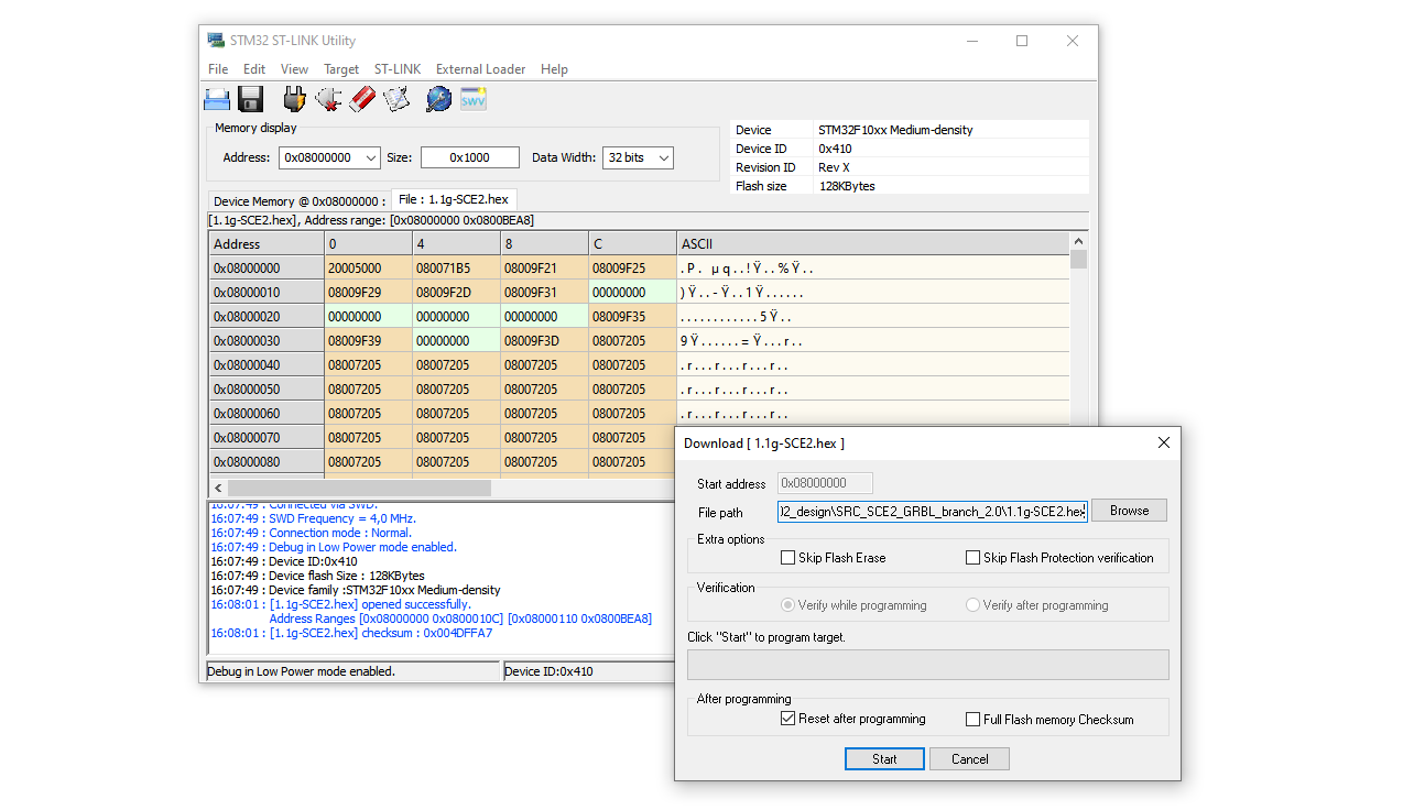](https://wiki.kurokesu.com/uploads/images/gallery/2022-08/stlink-utility.png)
After the firmware update, internal EEPROM content is erased. Lens settings should be updated. Do not connect the lens before restoring settings! Reference parameters and tools for can be found [here](https://github.com/Kurokesu/SCE2-SDK/tree/main/01_send_parameters)
#### Firmware revisions
Binary firmware files can be downloaded from the [SCE2-SDK](https://github.com/Kurokesu/SCE2-SDK/tree/main/firmware) Github repository.
| **Version** | **Date** | **Changes** |
| 1.1f-SCE2 | 2022-01-19 | Initial public release version
|
| 1.1g-SCE2 | 2022-08-21 | Fixed axis homing issue
|
# Communication over USB
#### Drivers
Stock firmware registers as "STM32 Virtual COM". Most modern operating systems should work out of the box, but original drivers can be downloaded from [STMicroelectronics web page](https://www.st.com/en/development-tools/stsw-stm32102.html)
#### COM port
Firmware is configured to work at **115200 8N1** baud rate
#### Terminal program
Feel free to use favorite terminal program. For further demonstration will use [Terminal App](https://sites.google.com/site/terminalbpp/)
[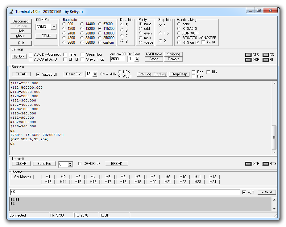](https://wiki.kurokesu.com/uploads/images/gallery/2020-09/terminal.png)
In some Windows cases Prolific USB to serial controller drivers can claim detected COM port, in this case uninstall driver and install downloaded from ST web page.
# Quick start guide
#### First motor moves
Assume axis has proper configuration sent earlier, making moves is as easy as entering command
In terminal bottom field type `G0 X10` and press `Enter`
[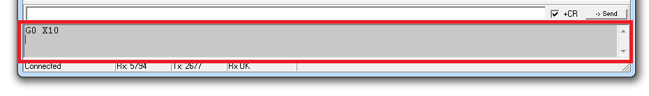](https://wiki.kurokesu.com/uploads/images/gallery/2020-09/terminal_1.png)
If linear actuator is connected it should move at **default max speed** by 10mm (rotary actuator should turn 10deg).
In order to move at different speeds G1 command should be used. For example `G1 Y10 F100`
List of supported G-code commands:
- **G0, G1:** Linear Motions
- **G2, G3:** Arc and Helical Motions
- **G4:** Dwell
- **G10 L2, G10 L20:** Set Work Coordinate Offsets
- **G17, G18, G19:** Plane Selection
- **G20, G21:** Units
- **G28, G30:** Go to Pre-Defined Position
- **G28.1, G30.1:** Set Pre-Defined Position
- **G38.2:** Probing
- **G38.3, G38.4, G38.5:** Probing
- **G40:** Cutter Radius Compensation Modes OFF (Only)
- **G43.1, G49:** Dynamic Tool Length Offsets
- **G53:** Move in Absolute Coordinates
- **G54, G55, G56, G57, G58, G59:** Work Coordinate Systems
- **G61:** Path Control Modes
- **G80:** Motion Mode Cancel
- **G90, G91:** Distance Modes
- **G91.1:** Arc IJK Distance Modes
- **G92:** Coordinate Offset
- **G92.1:** Clear Coordinate System Offsets
- **G93, G94:** Feedrate Modes
- **G100, G101:** TMC2300 register read/write
- **M0, M2, M30:** Program Pause and End
- **M3, M4, M5:** Spindle Control
- **M7**\* **, M8, M9:** Coolant Control
- **M56**\* **:** Parking Motion Override Control
Controller is shipped with X axis configured for RSB1 and X axis configured for LSA1 (0.635mm version)
#### Configuration
In order for controller to function correctly pulse count per revolution, acceleration and optionally motion limits has to be specified. In order to read configuration type `$$` and press `Enter`.
Recommended values for [LSA1 actuator](https://wiki.kurokesu.com/books/lsa1/page/grbl-motion-settings) and [RSB1 actuator](https://wiki.kurokesu.com/books/rsb1/page/grbl-motion-settings)
##### Read configuration parameters
All internal configuration parameters will be printed out. For example:
```shell
$0=6
$1=255
$2=0
$3=31
$4=1
$5=0
$6=0
$10=19
$11=0.010
$12=0.002
$13=0
$20=0
$21=0
$22=1
$23=15
$24=50.000
$25=200.000
$26=250
$27=5.000
$30=1000
$31=0
$32=0
$100=111.110
$101=1007.874
$102=17.778
$103=1536.000
$110=20000.000
$111=2500.000
$112=500000.000
$113=20000.000
$120=2000.000
$121=300.000
$122=40000.000
$123=1000.000
$130=360.000
$131=90.000
$132=360.000
$133=360.000
```
Detailed explanation can be found on [GRBL documentation](https://github.com/gnea/grbl/wiki/Grbl-v1.1-Configuration)
##### Write configuration parameters
Writing specific value is as easy as typing `$100=1000` and pressing `Enter` If number is valid, this command will overwrite existing value and save to EEPROM.
#### Control software
There are number of software packages suited to control CNC machines. Comprehensive list is maintained by [GRBL developers on GitHub](https://github.com/gnea/grbl/wiki/Using-Grbl). Our favorite is [**Candle** by Denvi](https://github.com/Denvi/Candle)
[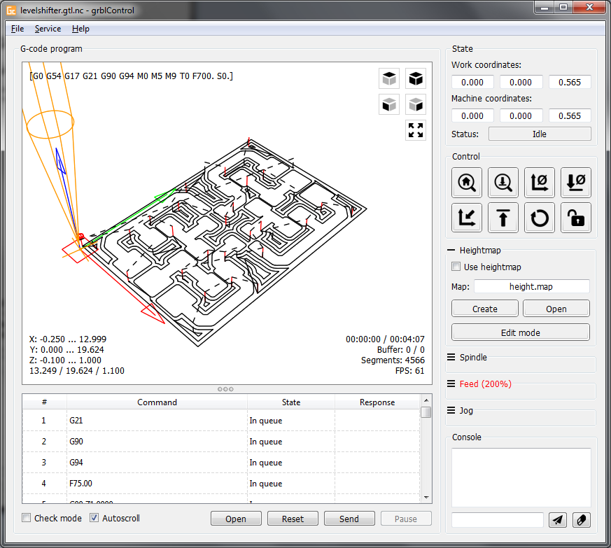](https://wiki.kurokesu.com/uploads/images/gallery/2020-09/screenshot_heightmap_original.png)# Some g-code examples and recipes
G-code while being universal machine control language has various flavors and capabilities. Below section is dedicated to speed up manual machine control with simple commands.
#### Move motors
There are two basic linear motion commands G0 and G1. Both are generally the same just G0 uses default max speed constant from configuration. Examples (assume linear actuator is connected):
| **Command** | **Explanation** |
| `G0 X100` | Move X axis to absolute position 100mm |
| `G1 X0 F100` | Move X axis to 0 position at speed 100mm/min |
#### Control GPIO pins
GRBL is designed for CNC machines and IO pins are used to make sense. Pin description is provided [here](https://wiki.kurokesu.com/books/sce2/page/pinout), but for actual functionality source code should be inspected.
| **Command** | **Explanation** |
| `M7` | MIST = ON |
| `M8` | FLOOD = ON |
| `M9` | MIST = OFF, FLOOD = OFF |
| **Command** | **Explanation** |
| `M3` | Set clockwise spindle rotation |
| `S300` | Set spindle control pin PWM duty cycle at 30% (max S = 1000) |
| `M4` | Set counter clockwise spindle rotation |
| `M5` | Turn spindle off |
#### Motor homing
After powering controller on it does not know motor position, thus it should be driven to home reference position
| **Command** | **Explanation** |
| `$HX` | Initialize X axis |
#### Read controller status
Almost any time controller status can be read with command `?`. It will report motor status (Idle/Run), actual positions and some other info.
| **Command** | **Output** |
| `?` | `` |
#### Read firmware version string
Functionality between versions will vary, some firmware versions or branches can have special functionality.
| **Command** | **Output** |
| `$I` | `[VER:1.1f-SCE2.20200405:]`
`[OPT:VMZHL,35,254]`
`ok` |
#### Probing
Firmware allows use of touch trigger probes. Moves down Z axis and stops on when probe pin is triggered, then reports collision point.
| **Command** | **Explanation and Output** |
| `G38.2 F100 Z-100` | Move down Z axis until PROBE pin is triggered
- F - Speed
- Z - Target depth
Replies with `[PRB:1.503,0.000,-22.860,0.000:1]`
|
#### Idle / wait
Idle command is useful for certain operations where controller needs to wait and do nothing (for example wait till spindle speeds up).
| **Command** | **Explanation** |
| `G4 P1.5` | Wait 1.5 seconds, reply with `ok` when done |
#### Read write parameters
Controller has quite a few parameters that can be set in EEPROM. See original description [here](https://github.com/gnea/grbl/blob/master/doc/markdown/settings.md).
| **Command** | **Explanation and Output** |
| `$$` | Read parameters
`$0=6`
`$1=255`
`$2=0`
`$3=31`
`...`
`$132=360.000`
`$133=360.000`
`ok`
|
| `$132=100.00` | Set single paramter with the new value
Replies with `ok`
|
#### Extra commands
Extra GPIO control commands used in motorized zoom lenses (L084, L0117, ...).
| **Command** | **Explanation and Output** |
| `M113 Px` | Control GPIO IO3, replies with `ok` |
| `M114 Px` | Control GPIO IO4, replies with `ok` |
| `M115 Px` | Control GPIO IO5, replies with `ok` |
| `M116 Px` | Control GPIO IO6, replies with `ok` |
| `M117 Px` | Control GPIO IO7, replies with `ok` |
| `M120 Px` | Control GPIO LIM\_EN, replies with `ok` |
Where X is 0 or 1# Reading and writing TMC2300 registers
Firmware has implemented functionality to read and write individual Trinamic TMC2300 registers over internal UART single wire interface. It shares transmit and receive line like an RS485 based interface. Data transmission is secured using a cyclic redundancy check and each TMC2300 driver is addressed individually as follows:
| **Axis** | **Address** |
| X | 0 |
| Y | 1 |
| Z | 2 |
| A | 3 |
| Broadcast to all axes | **9** |
Official TMC2300 [documentation](https://www.trinamic.com/products/integrated-circuits/details/tmc2300-la/)
All numbers in g-code arguments are decimal base numbers
#### Write registers
Write register command forwards g-command arguments to TMC2300 configuration interface. While it is not recommended because of stability issues, write command can be sent even if motors are turning (G0, G1, ... commands)
7'th bit of TMC2300 register has to be set to 1, thus for example **0x10** IHOLD\_IRUN becomes **0x90**
| **G100** | **P**<xx> | **L**<xx> | **N**<xx> | **S**<xx> | **F**<xx> | **R**<xx> |
| G-command | TMC2300 address | TMC2300 register (mask with 0x80) | DATA3 | DATA2 | DATA1 | DATA0 |
[](https://wiki.kurokesu.com/uploads/images/gallery/2020-09/tmc2300_write2.png)
Required checksum is calculated in firmware
#### Read registers
Read registers command has two arguments TMC2300 address and register address. It responds to terminal immediately.
| **G101** | **P**<xx> | **R**<xx> |
| G-command | TMC2300 address | TMC2300 register |
Response is decimal coded 12 bytes. Sample reply looks like this: `[TMC:5,0,16,112,5,255,16,0,0,0,0,157]`
| **Reply byte** | **Meaning** |
| 0 | Echo transmit byte0 |
| 1 | Echo transmit byte0 |
| 2 | Echo transmit byte0 |
| 3 | Echo transmit byte0 |
| 4 | Reply from TMC2300 sync (0x05) |
| 5 | Address |
| 6 | Register |
| 7 | Data byte3 |
| 8 | Data byte2 |
| 9 | Data byte1 |
| 10 | Data byte0 |
| 11 | Checksum |
[](https://wiki.kurokesu.com/uploads/images/gallery/2020-09/tmc2300_read2.png)
#### Examples
##### Set motor X current
Each motor driver can drive different motor. Power and other settings can be set individually. For example IHOLD\_IRUN (0x10) register controls motor idle, run and timing parameters.
`G100 P0 L144 N0 S0 F10 R5`
| G100 | Write to TMC2300 g-command |
| P0 | Driver address = 0 (X axis)
|
| L144 | TMC2300 register IHOLD\_IRUN (0x10)
**0x10** ->(set 7'th bit to 1)-> **0x90** = **144** (dec)
|
| N0 | Data3 = 0 (not used) |
| S0 | Data2 = 0 (see **IHOLDDELAY** in table below) |
| F10
| Data1 = 10 (see **IRUN** in table below) |
| R5 | Data0 = 5 (see **IHOLD** in table below) |
[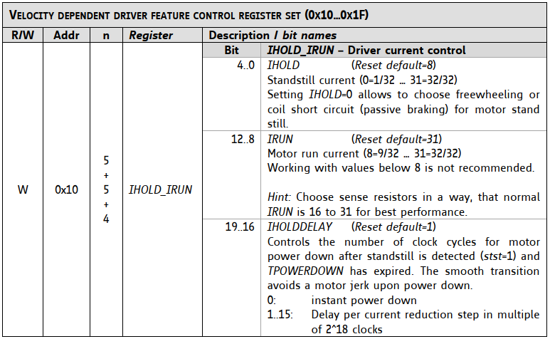](https://wiki.kurokesu.com/uploads/images/gallery/2020-09/tmc2300_pwr_registers2.png)
##### Read input register
Each TMC2300 driver has input status registers GSTAT (0x01) indicating over temperature, short circuit, and more.
`G101 P0 R1`
Response looks like:
`[TMC:5,0,1,193,5,255,1,0,0,0,1,154]`
Response contains only 3 bits of useful information. See explanation in table below.
[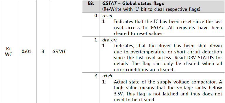](https://wiki.kurokesu.com/uploads/images/gallery/2020-09/tmc2300_status.png)# Automating tasks
#### Python g-code sender
Automating tasks can be done with Python script. Below is script example to send commands provided in text file:
```Python
import time
import os
from tqdm import tqdm
import serial
import argparse
parser = argparse.ArgumentParser()
parser.add_argument('-p','--port', help='COM port', required=True)
parser.add_argument('-f','--file', help='File name', required=True)
args = parser.parse_args()
ser = serial.Serial()
ser.port = str(args.port)
ser.baudrate = 115200
ser.timeout = 10
ser.open()
ser.flushInput()
ser.flushOutput()
print("Reading file...")
lines = []
with open(args.file) as fp:
for cnt, line in enumerate(fp):
lines.append(line)
print("Sleeping 1s...")
time.sleep(1)
for line in tqdm(lines):
l = bytes(line.strip()+ '\n', 'utf8')
ser.write(l)
grbl_out = ser.readline()
```
Text file example:
```shell
G91
M7
M8
G1 X45 F20000
M9
G1 X45 F20000
M8
G1 X45 F20000
M9
G1 X45 F20000
M8
G1 X45 F20000
M9
G1 X45 F20000
M8
G1 X45 F20000
M9
G1 X45 F20000
G90
```# SCE2-BREAKOUT demo board
**SCE2-BREAKOUT** is a fully integrated stepper motor controller module carrier board for quick SCE2-M module evaluation. Designed for small 3D printers, laser cutters/engravers, CNC mills, pick and place machines, robots, test fixtures, and other motorized devices. SCE2-M module is the smallest motor controller that requires no external components and runs industry-standard g-code processor with linear interpolation control open-source firmware. [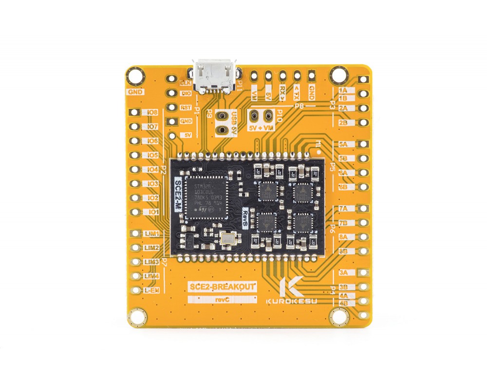](https://wiki.kurokesu.com/uploads/images/gallery/2020-08/Kurokesu-SCE2-breakout-1-1000x800.jpg)
#### Schematics
[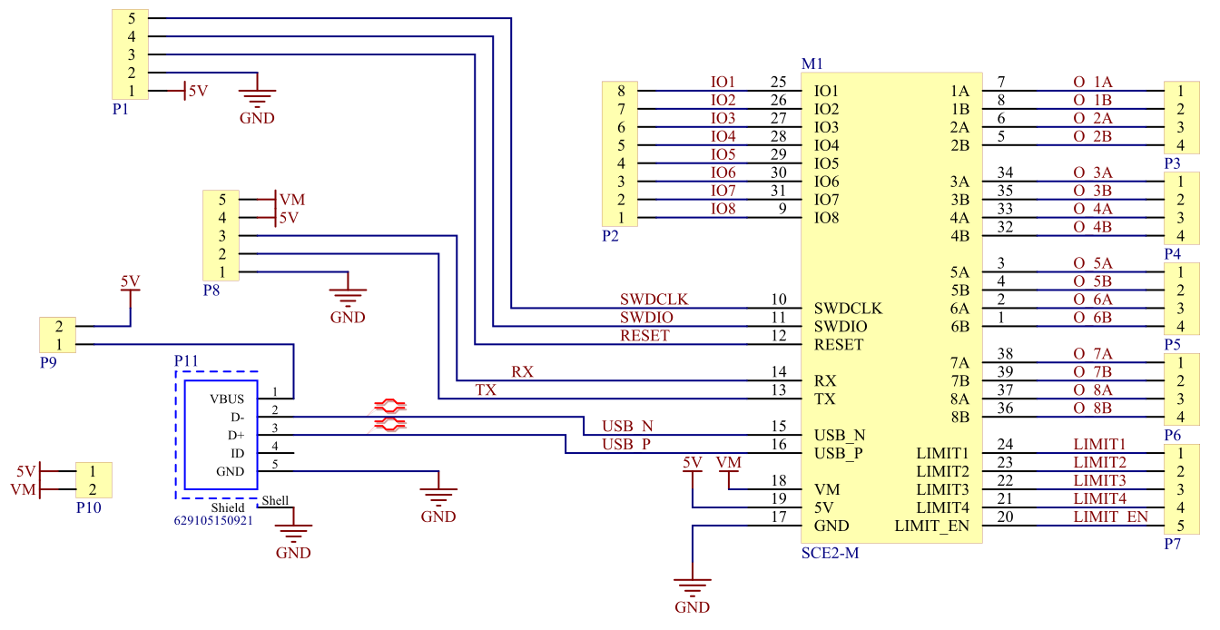](https://wiki.kurokesu.com/uploads/images/gallery/2020-09/SchematicPrints.png)
P9 is breaks power supply from USB port. Should be disconnected if power is applied via P8 header
P10 bridges 5V and VM. Should be disconnected if VM is applied via P8
#### Dimensions
[](https://wiki.kurokesu.com/uploads/images/gallery/2020-09/zc2SCE2_BREAKOUT.png)
3D STEP file is maintained on [Github](https://github.com/Kurokesu/3d_models)
# SCE2_dual_L012 dual lens controller board
**SCE2\_dual\_L012** is a fully integrated stepper motor controller module carrier board for controlling two motorized lens zoom/focus parameters. Controller requires only 5V power supply from the USB port and controlled with text-based G-code commands over USB or optionally TTL UART.
[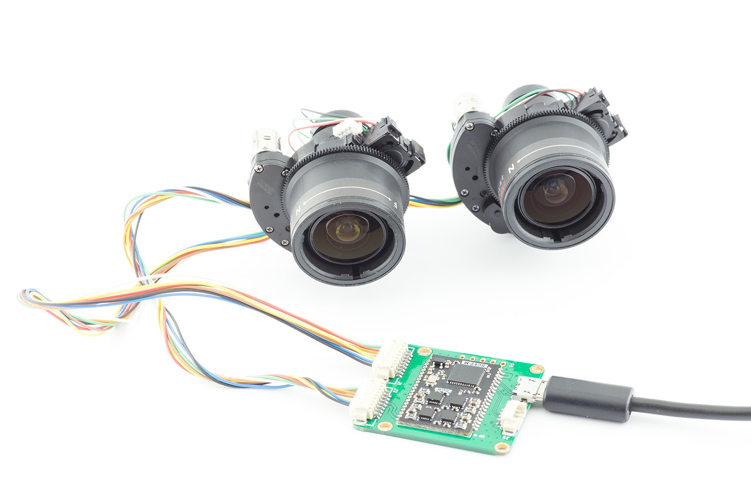](https://wiki.kurokesu.com/uploads/images/gallery/2021-01/IMG_2458_r.jpg)
#### Schematics
[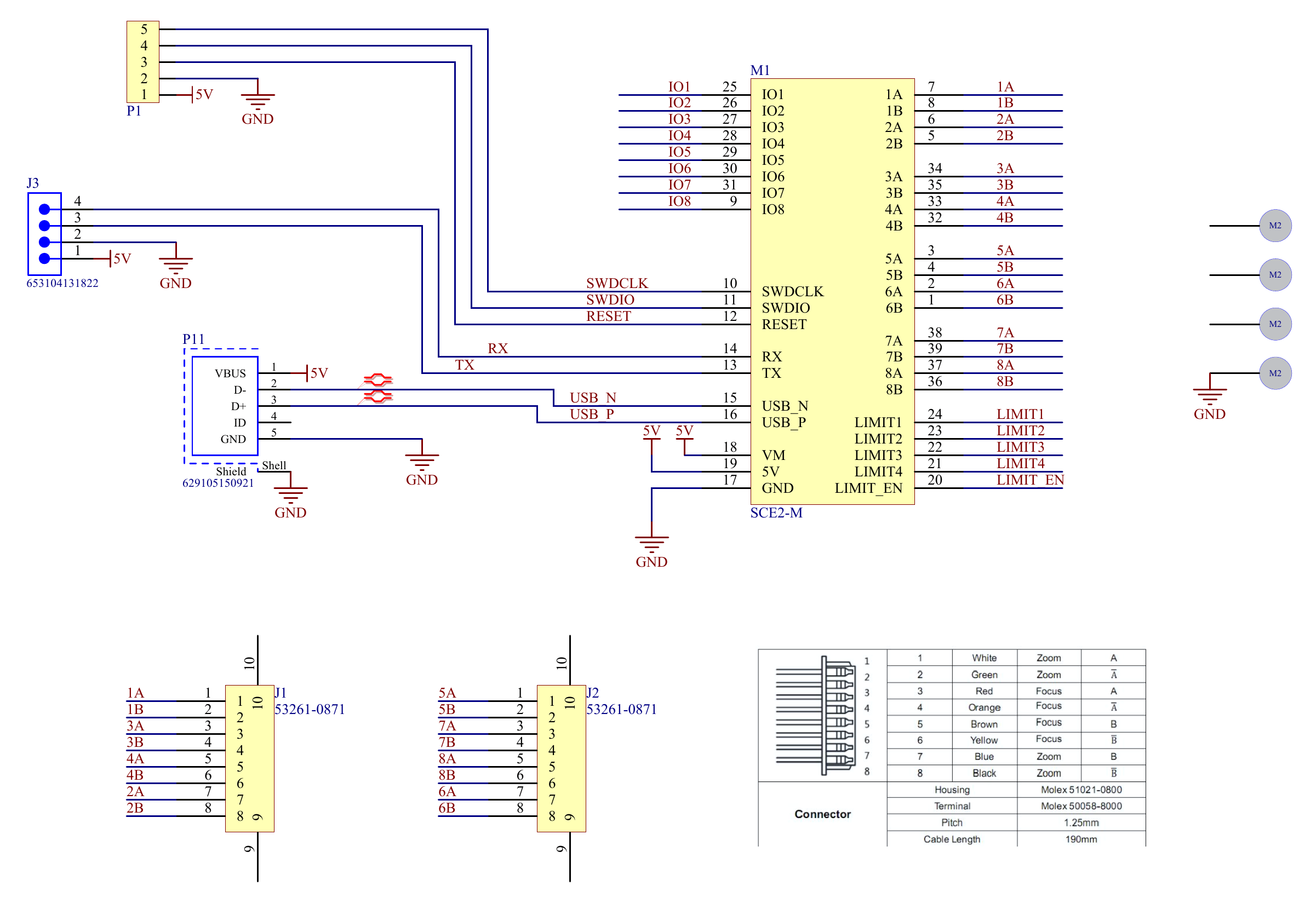](https://wiki.kurokesu.com/uploads/images/gallery/2021-01/SCE2_dual_L012.png)
#### Motor wiring vs axis definition
| **Axis** | **Motor function** | **Connector** |
| X | Focus | J1 |
| Y | Zoom | J1 |
| Z | Focus | J2 |
| A | Zoom | J2 |
#### Controlling the lenses
##### Recommended GRBL settings
Controller is shipped with default settings as listed below.
```shell
$0=6
$1=255
$2=0
$3=31
$4=1
$5=0
$6=0
$10=19
$11=0.010
$12=0.002
$13=0
$20=0
$21=0
$22=1
$23=15
$24=50.000
$25=200.000
$26=250
$27=5.000
$30=1000
$31=0
$32=0
$100=111.110
$101=111.110
$102=111.110
$103=111.110
$110=50000.000
$111=50000.000
$112=50000.000
$113=50000.000
$120=5000.000
$121=5000.000
$122=5000.000
$123=5000.000
$130=360.000
$131=360.000
$132=360.000
$133=360.000
$N0=G100P9L144N0S0F1R1
```
##### Startup sequence
Default TMC2300 power is too high for small stepper motors and will overheat and damage them. Motor drive/sleep current has to be decreased with commands listed below:
```shell
G100 P0 L144 N0 S0 F1 R1
G100 P1 L144 N0 S0 F1 R1
G100 P2 L144 N0 S0 F1 R1
G100 P3 L144 N0 S0 F1 R1
```
Or in a single command (valid since 20200103 firmware update)
```shell
G100 P9 L144 N0 S0 F1 R1
```
Which then can be added in GRBL startup sequence `$N0=G100P9L144N0S0F1R1`
##### Homing sequence
Lenses have no limit switches, thus precision homing is not possible. Instead each motor is driven to max position until hard stop and it is assumed that home position is achieved.
```shell
G91 # set motion to relative coordinate system
F30000 # set default motion speed
G1 X-500
G1 Y-1200
G1 Z-500
G1 A-1200
G90 # set motion to absolute coordinate system
G92 X0 Y0 Z0 A0 # set current position as 0
```
##### Control sequence
If power settings are reduced in startup stage, lens motors can be operated right away. Standard G-code motion commands can be used to drive motors. For example:
```shell
G1 Y100 A100 F40000
G1 Y-100 A100 F40000
G1 Y100 A-100 F40000
G1 Y-100 A-100 F10000
```
#####
#### Dimensions
[](https://wiki.kurokesu.com/uploads/images/gallery/2021-01/V3ISCE2_dual_L012.png)
Mounting hole diameter is (not indicated) in drawing is 2.3mm
3D STEP file is maintained on [Github](https://github.com/Kurokesu/3d_models)
# Precautions and disclaimers
## General disclaimer
- ALL PRODUCTS, PRODUCT SPECIFICATIONS, AND DATA ARE SUBJECT TO CHANGE WITHOUT NOTICE TO IMPROVE RELIABILITY, FUNCTION OR DESIGN OR OTHERWISE
- Kurokesu UAB, its affiliates, agents, and employees, and all persons acting on its or their behalf (collectively, "Kurokesu"), disclaim any and all liability for any errors, inaccuracies or incompleteness contained in any datasheet or any other disclosure relating to any product.
- The Information given herein is believed to be accurate and reliable. However, users should independently evaluate the suitability of and test each product selected for their applications
- See Kurokesu standard terms and conditions for warranty and other information
## Precautions
- Do not short circuit any part of the module
- Do not exceed nominal input
- Do not overload outputs
- Keep the module dry
- Observe the electrostatic discharge (ESD) precautions when handling the product. Damage caused by non-observance of the above instructions is not covered by the warranty
- Power electronics equipped with thermal shutdown circuitry, but if controller becomes too hot disconnect it
- Module is designed exclusively for installation into a device or housing to prevent external influences such as humidity/water or dirt
- Add active and/or passive power filtering circuitry in an electromagnetically noisy environment if a module becomes unstable
- Add active and/or passive power filtering circuitry if module exceeds allowed EMC emissions