SCE2_dual_L012 dual lens controller board
SCE2_dual_L012 is a fully integrated stepper motor controller module carrier board for controlling two motorized lens zoom/focus parameters. Controller requires only 5V power supply from the USB port and controlled with text-based G-code commands over USB or optionally TTL UART.

Schematics

Motor wiring vs axis definition
| Axis | Motor function | Connector |
| X | Focus | J1 |
| Y | Zoom | J1 |
| Z | Focus | J2 |
| A | Zoom | J2 |
Controlling the lenses
Recommended GRBL settings
Controller is shipped with default settings as listed below.
$0=6
$1=255
$2=0
$3=31
$4=1
$5=0
$6=0
$10=19
$11=0.010
$12=0.002
$13=0
$20=0
$21=0
$22=1
$23=15
$24=50.000
$25=200.000
$26=250
$27=5.000
$30=1000
$31=0
$32=0
$100=111.110
$101=111.110
$102=111.110
$103=111.110
$110=50000.000
$111=50000.000
$112=50000.000
$113=50000.000
$120=5000.000
$121=5000.000
$122=5000.000
$123=5000.000
$130=360.000
$131=360.000
$132=360.000
$133=360.000
$N0=G100P9L144N0S0F1R1
Startup sequence
Default TMC2300 power is too high for small stepper motors and will overheat and damage them. Motor drive/sleep current has to be decreased with commands listed below:
G100 P0 L144 N0 S0 F1 R1
G100 P1 L144 N0 S0 F1 R1
G100 P2 L144 N0 S0 F1 R1
G100 P3 L144 N0 S0 F1 R1
Or in a single command (valid since 20200103 firmware update)
G100 P9 L144 N0 S0 F1 R1Which then can be added in GRBL startup sequence $N0=G100P9L144N0S0F1R1
Homing sequence
Lenses have no limit switches, thus precision homing is not possible. Instead each motor is driven to max position until hard stop and it is assumed that home position is achieved.
G91 # set motion to relative coordinate system
F30000 # set default motion speed
G1 X-500
G1 Y-1200
G1 Z-500
G1 A-1200
G90 # set motion to absolute coordinate system
G92 X0 Y0 Z0 A0 # set current position as 0
Control sequence
If power settings are reduced in startup stage, lens motors can be operated right away. Standard G-code motion commands can be used to drive motors. For example:
G1 Y100 A100 F40000
G1 Y-100 A100 F40000
G1 Y100 A-100 F40000
G1 Y-100 A-100 F10000
Dimensions
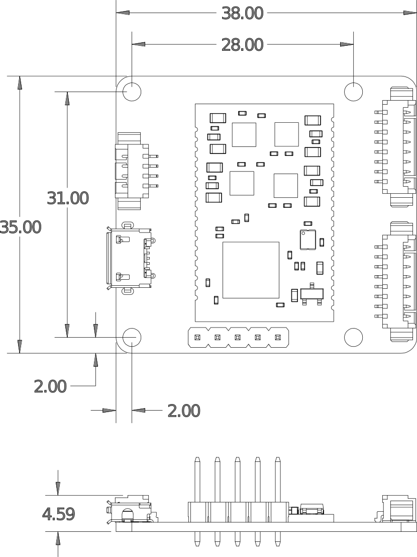
Mounting hole diameter is (not indicated) in drawing is 2.3mm
3D STEP file is maintained on Github