# SCF4
# About
### General Description
Tiny self-sufficient stepper motor controller **SCF4-M** module is designed for high integration customer products and can drive FIZ+ lens with 3 stepper motors (for example Focus/Zoom/P-Iris with micro-stepping up to 1/1024 steps for inaudible operation) and IR filter simultaneously. Also has 3 limit switch inputs and 4 GPIO (IN/OUT/ADC) pins for custom application control. The controller expects industry-standard G-code formatted commands for fastest and easiest integration. Designed to be connected over single USB cable (USART and I2C can be supported in custom firmware). Firmware modifications can be tailored to suit customer requirements. SCF4 - is a one in a series of Kurokesu stepper motor controllers and stands for Stepper Controller Model F, 4'th modification.
### Features
- Small footprint 16 x 23 x 2.3 mm \[0.63 x 0.91 x 0.09 in\]
- 3x stepper motor controller with up to 1/1024 micro-stepping support for each motor
- 1x H-bridge for coil control (day/night filter switch)
- 3x limit switch processing for precise lens homing/referencing
- Direct USB Full-speed (12 Mbit/s) connectivity
- 4x GPIO's with Input/Output/Analog functionality
- Industry standard G-code command set
- Can drive most lenses with bipolar stepper motors with minor or none tuning
- Certificates: REACH, RoHS, CE
### Applications
- Motorized zoom lenses
- Small test fixtures
- Micro mechanism control# SCF4-M module
## Pin description
[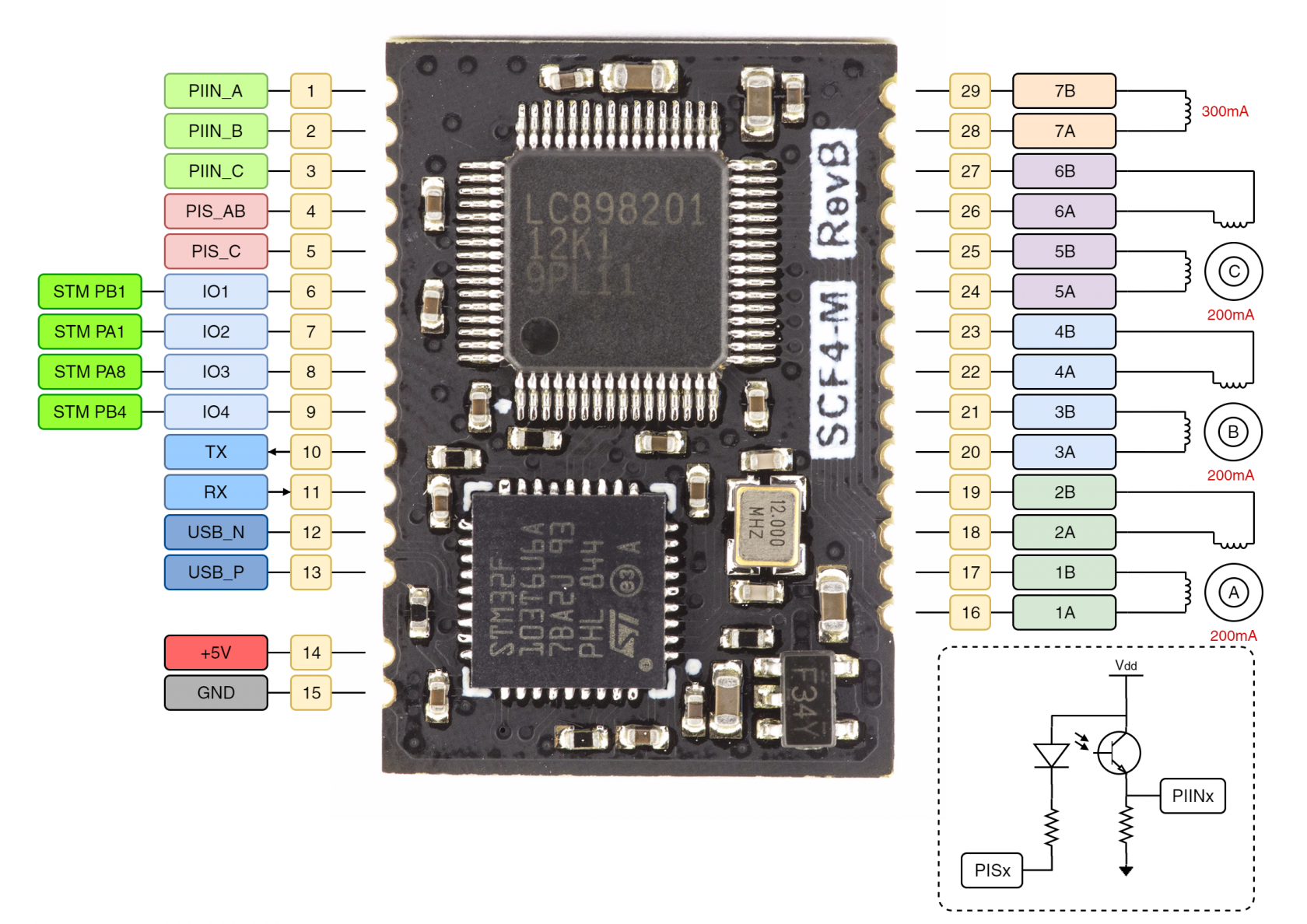](https://wiki.kurokesu.com/uploads/images/gallery/2021-01/SCF4-M_motor_diagram.png)
## Technical specifications
| Module dimensions | 16 x 23 x 2.3 mm \[0.63 x 0.91 x 0.09 in\] |
| Controlled stepper motors | 3 |
| Connectivity | **USB** (optional USART, I2C, SPI) |
| Module pin count | 29 |
| Stepper motor resolution | up to 1/1024 micro-steps (1/64 default) |
| PWM voltage levels for filter switch | H-Bridge (128 voltage levels) |
| Weight | 0.9g |
| Power consumption (module only) | 55mA @ 5V |
| Power consumption (operating x18 lens 2 motors) | 180mA @ 5V |
## Absolute maximum ratings
| Min supply voltage | 4.3 | V |
| Max supply voltage | 7.0
| V |
| Stepper motor max current | 200 | mA @ 5V |
| IR Filter coil max current | 300 | mA @ 5V |
## Operating parameters
| Operating voltage | 4.5 ~ 5.5 | V |
| Controller max current consumption | 1 | A @ 5V |
| Controller power rating | 5 | W |
| Relative Humidity | Non-Condensing | |
| Operating Temperature | -40 ~ 85 | °C |
## Mechanical dimensions
[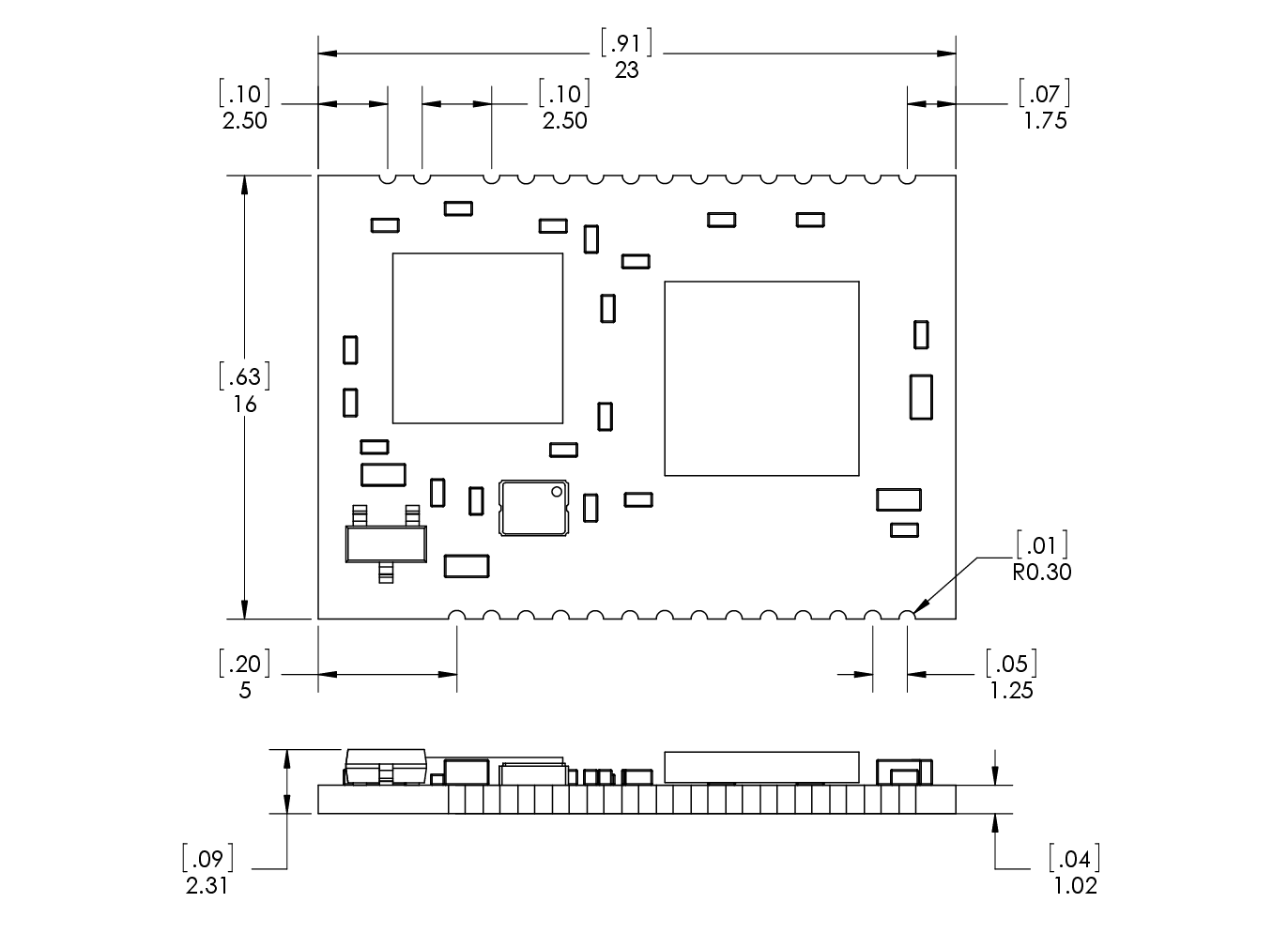](https://wiki.kurokesu.com/uploads/images/gallery/2021-01/SCF4M_dimensions.png)
## Test points
For testing, flashing firmware and post-production purposes SCF4-M module has several test points.
[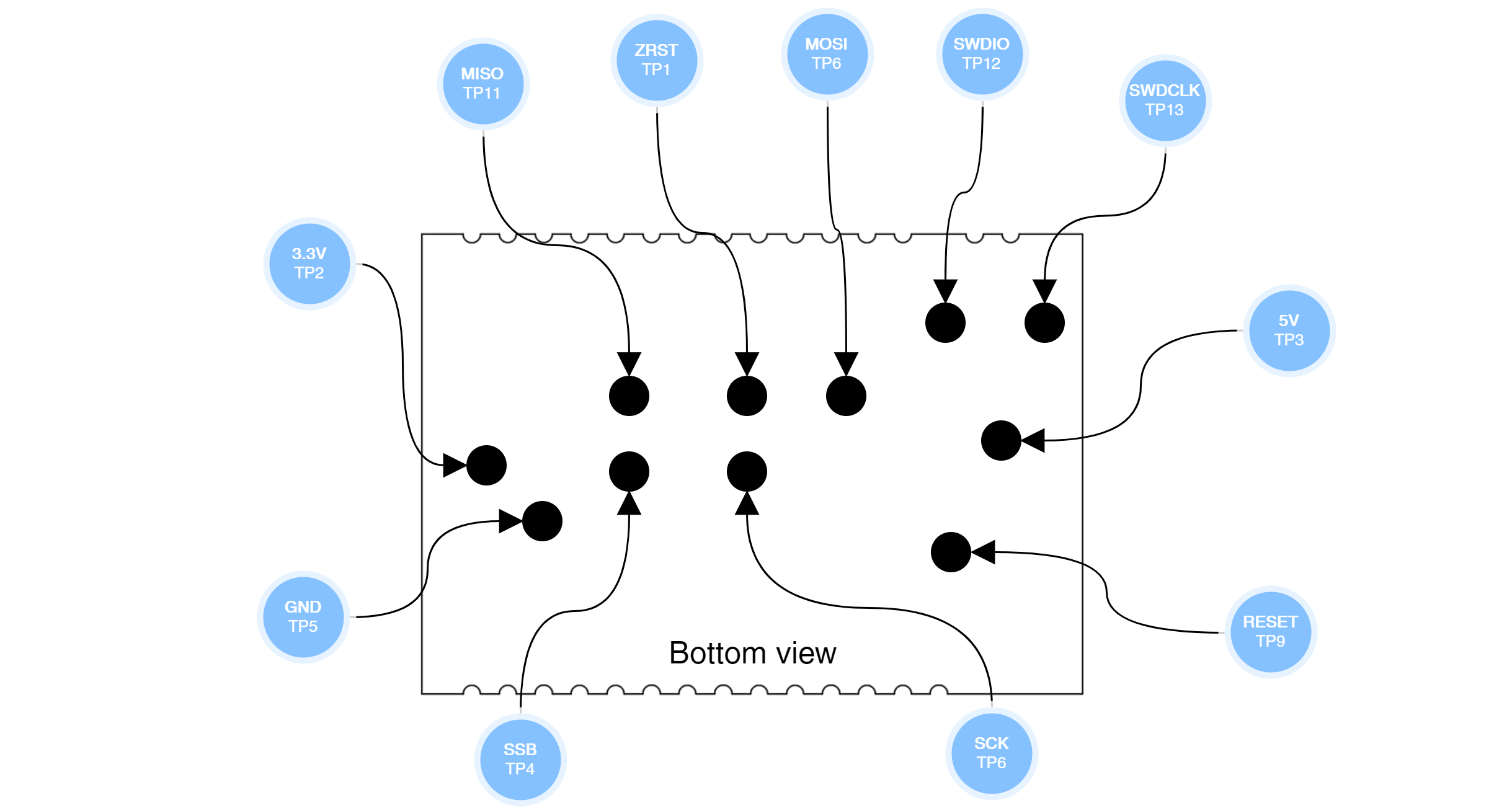](https://wiki.kurokesu.com/uploads/images/gallery/2021-01/SCF4-M-tps.png)
For exact dimensions and locations check 3D STEP file.# Controlling SCF4 with G-code commands
FIZ+ controller expects industry-standard G-code formatted commands. Commands are text-based and human-readable. Some highlights and behavior notes:
- Controller has limited buffer/cache functionality, a user should rely on single command execution at a time. Each command ends with a response
- Controller never sends commands back to the computer without asking
- `G1` linear interpolation is not supported, but it can be implemented by setting motion speeds and feeds manually
## G-code introduction
G-code is the common name for the most widely used numerical control (CNC) programming language. It tells the motors where to move, how fast to move, and what path to follow. G-code has many variants and each machine has unique behavior implementation. More details on G-code can be found at [https://en.wikipedia.org/wiki/G-code](https://en.wikipedia.org/wiki/G-code)
## Index of supported G-code commands
Below is a list of supported commands. For a detailed explanation and usage examples see next section.
### Version strings and identification commands
| **Command** | **Description** | **Returns** |
| `$S` | Return version, sn, model and brand strings | See details below |
### Controller initialization
| **Command** | **Description** | **Returns** |
| `$B1` | Reset motor driver | `OK` |
| `$B2` | Reset and initialize motor driver | `OK` |
| `$B3` | Reset STM32F103 processor | `OK` |
### Motion commands
| **Command** | **Description** | **Returns** |
| `G0` | Rapid positionin | `OK` |
| `G4` | Wait / stall | after complete `OK` |
| `G90` | Absolute programming mode | `OK` |
| `G91` | Incremental programming mode | `OK` |
| `G92` | Set position | `OK` |
### Miscellaneous function
| **Command** | **Description** | **Returns** |
| `M0` | Compulsory stop | `OK` |
| `M7` | DN function with filter (VIS) | `OK` |
| `M8` | DN function no filter (IR + VIS) | `OK` |
| `M230` | Set normal move | `OK` |
| `M231` | Set normal + forced move | `OK` |
| `M232` | Set PI low/high detection voltage | `OK` |
| `M234` | Set motor and DN drive current | `OK` |
| `M235` | Set motor idle current | `OK` |
| `M238` | PI LED on (some lenses leak light into sensor) | `OK` |
| `M239` | PI LED off | `OK` |
| `M240` | Set motor drive speed | `OK` |
| `M245` | Drive AUX output to low (high resistance output) | `OK` |
| `M246` | Drive AUX output to high (low resistance output) | `OK` |
| `M247` | Read power supply voltage value | `ADC=xxxx` |
### Advanced function
| **Command** | **Description** | **Returns** |
| `M241` | Dividing setting 1 | `OK` |
| `M242` | Pulse generation control 1 | `OK` |
| `M243` | Microstepping | `OK` |
| `M244` | Dividing setting 2 | `OK` |
### Status commands
| **Command** | **Description** | **Returns** |
| `!1` | Return motor pos, limit sw, moving status | `4000, 20000, 0, 0, 0, 0, 0, 0` |
## Controlling SCF4 with G-code commands explanation and usage examples
### Axis description
Driver support bipolar stepper motors for 3 axes. They are named A/B/C and usually have defined function:
- A - zoom
- B - focus
- C - aperture
### `$S` - Return version string
Command returns version string concentrated into single line `EVB.1.0.2, SCF4-M RevB, Kurokesu, 5DDFF39-3739584E-xxxxxxxx` received information is comma separated:
- `EVB.1.0.2` - Module firmware version
- `SCF4-M RevB` - Module PCB revision
- `Kurokesu` - Manufacturer Brand
- `5DDFF39-3739584E-xxxxxxxx` - Unique serial number
### `G0` - Rapid positioning
The main motor drive command. It moves motor specified number steps. Any or all axes can be specified at the same time. Minimal step size is 1. `G0` command replies as soon as the command is parsed and does not wait until motors stop.
- `G0 A100` - drives A-axis 100 steps
- `G0 A-100` - drives A-axis -100 steps
- `G0 A100 B-100 C1000` - drives all three axes by specified step count
### `G4` - Wait
Instructs controller to delay (stall) defined interval in milliseconds \[ms\]. This is an only command which sends response not after parsing command but after prolonged execution time. During this time command parser is blocked and the only way to complete this command is to wait until it finishes.
### `G90` - Absolute coordinates
Switch to absolute coordinate programming mode. In this mode, the range is limited by the internal 16-bit motor register and can be operated in a range of 0 ~ 65535.
### `G91` - Relative coordinates
Switch to relative coordinate programming mode. Motors can be instructed to turn positive or negative 0 ~ 65535 steps (16-bits). When the counter exceeds this range, it will overflow. And will not affect motor movement.
### `G92` - Set position
The controller sets an internal counter to the specified value.
- `G92 A0` - Set A axis counter to 0
- `G92 A100` - Set A axis counter to 100
- `G92 A100 B1000 C200` - Set all axis counters to specified counter values
### `M0` - Compulsory stop
If the controller is not in G4 delay mode it will instruct motors to stop moving
### `M7` and `M8` - Infrared filter switch commands
Instructs controller to shift filter to one of two fixed positions
### `M230` and `M231` - normal / forced move
- Default is normal mode in which motors turn instructed step count and stop after
- In forced mode controller does not stop turning motor after specified step count is reached, instead seeks corresponding port PIN\_x status state change. Internal step counter may overflow. Motion is stopped when input status changes, `M0` or reset command is issued. PIN\_x is connected to internal 12bit Analog to Digital Converter (ADC), lower and upper thresholds can be controlled with `M232` command
### `M232` - Set PI low/high detection voltage
Set 12bit comparator values for limit switch detection inputs. Upper voltage is 3.3V, lower - 0V
- A, B, C - set lower threshold values
- E, F, G - set upper threshold values
- `M232 A1242 E2483` - If the input voltage is below ~1V - set flag to `0`. If the value is above ~2V, set flag to `1`. Everything in between - is hysteresis and does not change the flag. Used to debounce and filter the input signal
### `M234` - Set motor and DN drive current
Sets motor and coil drive current. Expects 8-bit value.
- `M234 A120 B120 C120 D80` - Set A, B, C stepper motors strength to 120 and IR filter driver to 80
### `M235` - Set motor idle current
When motors are not moving, idle current can be reduced to eliminate heating and save energy. It is not advised to completely turn off motors as the driver can lose micro-step holding position
- `M234 A50 B50 C50` - Sets A/B/C motors holding current to value 50
### `M238` and `M239` - control output pins
Opto-interrupter LEDs can be controlled by connecting them to PIS\_AB and PIS\_C pins. They can stay in either state, but some lenses in IR mode can leak light into the sensor so after referencing/calibration procedure is complete it is advised to switch them off
### `M240` - Set motor drive speed
Each motor can drive at different speeds. Speed is 16-bit register. Register specifies internal timing interval, the lower value is the faster pulse rate will be.
- `M240 A800 B800 C1200` - Set motion speeds for each axis to corsponding value
### `M241`, `M242`, `M243`, `M244` - advanced timing registers
- These registers control motor driver timing and should not be altered normally, however in some cases it can be necessary to make adjustments. Please seek the support if you have any questions
### `M245` - Drive AUX output to low
Command drives auxiliary output to high resistance state. This is default value after power up or CPU reset.
Feature added in EVB.1.1.0 firmware. Used in **SCF4-L090 revC** and **SCF4-L087 revB** boards.
### `M246` - Drive AUX output to high
Command drives auxiliary output to low resistance state.
Feature added in EVB.1.1.0 firmware. Used in **SCF4-L090 revC** and **SCF4-L087 revB** boards.
### `M247` - Read power supply voltage value
Command reads power supply voltage. Responds with 12bit decimal value.
Reference voltage is Vref=3.3
| **Symbol** | **Value** | **Units** | **Note** |
| Vref | 3.3 | V | |
| ADC\_TOP | 4096 | | 12bit max ADC value |
| SCALE | 0.5 | | Boards uses resistance divider |
| ADC | | | Value returned by command |
Conversion to voltage: Vin = ADC/4096\*Vref/DIV
Feature added in EVB.1.1.0 firmware. Used in **SCF4-L090 revC** and **SCF4-L087 revB** boards.
### `!1` - Return status
Command returns 9 values indicating:
- `4000, 20000, 0, 0, 0, 0, 0, 0` - example output
- A Motor position counter
- B Motor position counter
- C Motor position counter
- A Limit switch status
- B Limit switch status
- C Limit switch status
- A Moving status
- B Moving status
- C Moving status# Controlling over I2C port
Applies to EVB.1.2.0 firmware where I2C is implemented
Slave address: 0x33
#### About
In order to simplify I2C communication, firmware utilizes one one direction read/write operations. All commands expect 5 bytes, where first byte is function address, remaining bytes is payload.
USB-CDC works in parallel with I2C functionality and independently, but it is recommended to use single communication channel once controller is initialized.
#### Wiring
[](https://wiki.kurokesu.com/uploads/images/gallery/2020-08/MFPi2c_connection.png)
In order to avoid power loops, do not connect both (SCF4 and Arduino) USB ports at the same time.
#### Write data
All commands are fixed length consisting of 5 bytes.
| W: I2C ADDR | FUNCTION | BYTE1 | BYTE2 | BYTE3 | BYTE4 |
#### Read data
First issue write command (register values are ignored). This step performs necessary calculations and fills memory with registers ready for reading in next step.
| W: I2C ADDR | FUNCTION | BYTE1 | BYTE2 | BYTE3 | BYTE4 |
Read command also consists of 5 bytes. FUNCTION repeats last write command value.
| R: I2C ADDR | FUNCTION | BYTE1 | BYTE2 | BYTE3 | BYTE4 |
#### Commands
| **ADDR** | **REGISTER NAME** | **R/W** | **FUNCTION** |
| 0x02 | **RESET\_CPU** | W | Reset STM32 CPU |
| 0x03 | **INIT\_DRV** | W | Reset and initialize motor driver |
| 0x05 | **AUX\_OUT** | W | Control AUX output on/off |
| 0x06 | **MODE** | W | Normal / forced move |
| 0x07 | **STOP** | W | Compulsory stop |
| 0x08 | **PI\_LEDS** | W | Switch on ON or OFF PI LEDs |
| 0x09 | **MOTOR\_SLEEP\_PWR** | W | Set motor sleep power |
| 0x0A | **MOTOR\_DRV\_PWR** | W | Set motor working power |
| 0x0B | **MOTOR\_SPEED** | W | Set motor speed |
| 0x0C | **PI\_THRESHOLD** | W | Set PI detector thresholds |
| 0x0D | **READ\_STATUS** | R | Read controller status |
| 0x0E | **SET\_MOTOR\_POS** | W | Set current motor position |
| 0x0F | **SET\_MICROSTEPPING** | W | Set motor micro-stepping mode |
| 0x10 | **DN\_SWITCH** | W | IR fitler |
| 0x20 | **MOVE** | W | Move motor |
#### Command explanation
##### `RESET_CPU` - Reset CPU
Resets CPU. Other values are ignored.
| **Description** | **FUNCTION** | **BYTE1** | **BYTE2** | **BYTE3** | **BYTE4** |
| Reset CPU | 0x02 | ignored | ignored | ignored | **0x32** |
##### `INIT_DRV` - Reset motor driver
Resets and initializes motor controller. Other values are ignored.
| **Description** | **FUNCTION** | **BYTE1** | **BYTE2** | **BYTE3** | **BYTE4** |
| Initialize motor driver | 0x03 | ignored | ignored | ignored | **0x32** |
##### `AUX_OUT` - Control AUX output
Controls GPIO output
| **Description** | **FUNCTION** | **BYTE1** | **BYTE2** | **BYTE3** | **BYTE4** |
| Set AUX to Low | 0x05 | ignored | ignored | ignored | **0x00** |
| Set AUX to High | 0x05 | ignored | ignored | ignored | **0x01** |
##### `MODE` - Normal / forced move
Selects between normal and normal+forced move mode
| **Description** | **FUNCTION** | **BYTE1** | **BYTE2** | **BYTE3** | **BYTE4** |
| Normal move mode | 0x06 | ignored | ignored | **Channel** | **0x00** |
| Normal+Forced move mode | 0x06 | ignored | ignored | **Channel** | **0x01** |
Channel encoding:
| **Channel** | **BYTE3 value** |
| A | 0x01 |
| B | 0x02 |
| C | 0x03 |
##### `STOP` - Compulsory stop
Stop movement of all motors
| **Description** | **FUNCTION** | **BYTE1** | **BYTE2** | **BYTE3** | **BYTE4** |
| Reset CPU | 0x07 | ignored | ignored | ignored | **0x32** |
##### `PI_LEDS` - Switch on ON or OFF PI LEDs
Control LEDs used in homing procedure.
| **Description** | **FUNCTION** | **BYTE1** | **BYTE2** | **BYTE3** | **BYTE4** |
| OFF | 0x08 | ignored | ignored | ignored | **0x00** |
| ON | 0x08 | ignored | ignored | ignored | **0x01** |
##### `MOTOR_SLEEP_PWR` - Set motor sleep power
Set motor sleep current
| **Description** | **FUNCTION** | **BYTE1** | **BYTE2** | **BYTE3** | **BYTE4** |
| Set current | 0x09 | ignored | ignored | **Channel** | **Power** |
Channel encoding:
| **Channel** | **BYTE3 value** |
| A | 0x01 |
| B | 0x02 |
| C | 0x03 |
##### `MOTOR_DRV_PWR` - Set motor working power
Set motor operating current
| **Description** | **FUNCTION** | **BYTE1** | **BYTE2** | **BYTE3** | **BYTE4** |
| Set current | 0x0A | ignored | ignored | **Channel** | **Power** |
Channel encoding:
| **Channel** | **BYTE3 value** |
| A | 0x01 |
| B | 0x02 |
| C | 0x03 |
| D | 0x04 |
##### `MOTOR_SPEED` - Set motor speed
Set motor speed
| **Description** | **FUNCTION** | **BYTE1** | **BYTE2** | **BYTE3** | **BYTE4** |
| Set speed | 0x0B | ignored | **Channel** | **Speed \[15:8\]** | **Speed \[7:0\]** |
Channel encoding:
| **Channel** | **BYTE2 value** |
| A | 0x01 |
| B | 0x02 |
| C | 0x03 |
##### `PI_THRESHOLD` - Set PI detector thresholds
Set limit switch optocoupler detector thresholds
| **Description** | **FUNCTION** | **BYTE1** | **BYTE2** | **BYTE3** | **BYTE4** |
| Set threshold | 0x0C | ignored | **Channel** | **Signal \[15:8\]** | **Signal \[7:0\]** |
Channel encoding:
| **Channel** | **BYTE2 value** |
| A LOW | 0x01 |
| B LOW | 0x02 |
| C LOW | 0x03 |
| A HIGH | 0x04 |
| B HIGH | 0x05 |
| C HIGH | 0x06 |
##### `READ_STATUS` - Read controller status
Read motor status, PI status and motor positions
| **Description** | **FUNCTION** | **BYTE1** | **BYTE2** | **BYTE3** | **BYTE4** |
| Set current | 0x0D | ignored | ignored | ignored | **Channel** |
Channel encoding:
| **Channel** | **BYTE2 value** |
| A position | 0x01 |
| B position | 0x02 |
| C position | 0x03 |
| PI\_A status | 0x04 |
| PI\_B status | 0x05 |
| PI\_C status | 0x06 |
| A moving | 0x07 |
| B moving | 0x08 |
| C moving | 0x09 |
Returns:
| **Description** | **FUNCTION** | **BYTE1** | **BYTE2** | **BYTE3** | **BYTE4** |
| Status return value | 0x0D | **Value \[31:24\]** | **Value \[23:16\]** | **Value \[15:8\]** | **Value \[7:0\]** |
##### `SET_MOTOR_POS` - Set position
Redefine current position
| **Description** | **FUNCTION** | **BYTE1** | **BYTE2** | **BYTE3** | **BYTE4** |
| Set position | 0x0E | **Channel** | **Speed \[23:16\]** | **Speed \[15:8\]** | **Speed \[7:0\]** |
Channel encoding:
| **Channel** | **BYTE1 value** |
| A | 0x01 |
| B | 0x02 |
| C | 0x03 |
##### `SET_MICROSTEPPING` - Set microstepping mode
Set microstepping mode for defined channel
| **Description** | **FUNCTION** | **BYTE1** | **BYTE2** | **BYTE3** | **BYTE4** |
| Set microstepping | 0x0F | ignored | ignored | **Channel** | **Mode** |
Channel encoding:
| **Channel** | **BYTE1 value** |
| A | 0x01 |
| B | 0x02 |
| C | 0x03 |
##### `MOVE` - Move motor
Move motor defined step count.
| **Description** | **FUNCTION** | **BYTE1** | **BYTE2** | **BYTE3** | **BYTE4** |
| Steps | 0x20 | **Channel** | **Direction** | **Steps \[15:8\]** | **Steps \[7:0\]** |
Channel encoding:
| **Channel** | **BYTE2 value** |
| A | 0x01 |
| B | 0x02 |
| C | 0x03 |
MAX steps is: 0xFFFF-1 = **0xFFFE**
Theia lens exceeds 0xFFFF step count, thus absolute positioning has to be implemented on client side code
##### `DN_SWITCH` - IR filter swith
Switch filter to day or night position
| **Description** | **FUNCTION** | **BYTE1** | **BYTE2** | **BYTE3** | **BYTE4** |
| POS1 | 0x10 | ignored | ignored | ignored | **0x00** |
| POS2 | 0x10 | ignored | ignored | ignored | **0x01** |
#### Arduino sketch example
Demo output should look like
```shell
SCF4-M I2C tester
Init driver
Set microstepping
Move mode
PI LEDS
Set drive pwr
Set sleep pwr
Set motor speeds
Set PI thresholds
Read status: posA
D 0 0 0 0
Read status: PI A
D 0 0 0 1
Homing A
Homing B
Move +A
Move -A
Move +B
Move -B
Move +C
Move -C
Set position
DN 0
DN 1
DN 0
DN 1
Last return from I2C port: ok
Loop...
```
`tester.ino`
```C
#include
#define CH_A 0x01
#define CH_B 0x02
#define CH_C 0x03
#define CH_D 0x04
#define CCW 0
#define CW 1
void err_print(byte err)
{
if (err == 0)
{
Serial.println("ok");
}
else if (err==4)
{
Serial.println("failed");
}
}
void setup()
{
Wire.begin();
Serial.begin(115200);
while (!Serial);
Serial.println("\nSCF4-M I2C tester\n");
}
void loop()
{
byte error;
Serial.println("Init driver");
SCF4_INIT_DRIVER();
Serial.println("Set microstepping");
SCF4_MICROSTEPPING(2, CH_A);
SCF4_MICROSTEPPING(2, CH_B);
SCF4_MICROSTEPPING(6, CH_C);
Serial.println("Move mode");
SCF4_MODE(0x00, CH_A);
SCF4_MODE(0x00, CH_B);
SCF4_MODE(0x00, CH_C);
Serial.println("PI LEDS");
SCF4_PI_LEDS(0x01);
Serial.println("Set drive pwr");
SCF4_DRV_PWR(180, CH_A);
SCF4_DRV_PWR(180, CH_B);
SCF4_DRV_PWR(180, CH_C);
SCF4_DRV_PWR(90, CH_D);
Serial.println("Set sleep pwr");
SCF4_SLEEP_PWR(50, CH_A);
SCF4_SLEEP_PWR(50, CH_B);
SCF4_SLEEP_PWR(50, CH_C);
Serial.println("Set motor speeds");
SCF4_MOTOR_SPEED(5000, CH_A);
SCF4_MOTOR_SPEED(5000, CH_B);
SCF4_MOTOR_SPEED(5000, CH_C);
Serial.println("Set PI thresholds");
SCF4_PI_THRESHOLD(2000, 0x01);
SCF4_PI_THRESHOLD(2000, 0x02);
SCF4_PI_THRESHOLD(2000, 0x03);
SCF4_PI_THRESHOLD(3000, 0x04);
SCF4_PI_THRESHOLD(3000, 0x05);
SCF4_PI_THRESHOLD(3000, 0x06);
Serial.println("Read status: posA");
SCF4_READ_STATUS(0x01);
Serial.println("Read status: PI A");
SCF4_READ_STATUS(0x04);
Serial.println("Homing A");
MOVE(30000, CW, CH_A);
delay(2000);
SCF4_MODE(0x01, CH_A);
MOVE(0x100, CCW, CH_A);
delay(15000); // status reading is not implemented, for testing 15s timeout is used
SCF4_MODE(0x00, CH_A);
SET_MOTOR_POS(100, CH_A);
Serial.println("Homing B");
MOVE(30000, CW, CH_B);
delay(2000);
SCF4_MODE(0x01, CH_B);
MOVE(0x100, CCW, CH_B);
delay(15000); // status reading is not implemented, for testing 15s timeout is used
SCF4_MODE(0x00, CH_B);
SET_MOTOR_POS(100, CH_B);
// normal operation starts here
Serial.println("Move +A");
MOVE(0xFFFE, CW, CH_A);
delay(5000);
Serial.println("Move -A");
MOVE(0xFFFE, CCW, CH_A);
delay(5000);
Serial.println("Move +B");
MOVE(0xFFFE, CW, CH_B);
delay(5000);
Serial.println("Move -B");
MOVE(0xFFFE, CCW, CH_B);
delay(5000);
Serial.println("Move +C");
MOVE(1000, CW, CH_C);
delay(2000);
Serial.println("Move -C");
MOVE(1000, CCW, CH_C);
delay(2000);
Serial.println("Set position");
//SET_MOTOR_POS(100, 0x01);
//SET_MOTOR_POS(200, 0x01);
//SET_MOTOR_POS(300, 0x01);
//STOP();
Serial.println("DN 0");
DN_SWITCH(0);
delay(1000);
Serial.println("DN 1");
DN_SWITCH(1);
delay(1000);
Serial.println("DN 0");
DN_SWITCH(0);
delay(1000);
Serial.println("DN 1");
DN_SWITCH(1);
delay(1000);
Serial.print("Last return from I2C port: ");
err_print(error);
Serial.println("Loop...");
while(1)
{
}
}
```
`scf4_i2c.ino`
```C
// SCL - A5
// SDA - A4
#include
#define SCF4_ADDR 0x33
// SCF4 is not signaling busy status, thus fixed delay is added
// If next I2C command is sent too soon it might be ignored
#define I2C_SLEEP 200
byte SCF4_AUX(byte status)
{
byte function = 0x05;
byte error;
//byte w1 = (counter&0xFF);
//byte w2 = ((counter>>8)&0xFF);
//byte w3 = ((counter>>16)&0xFF);
//byte w4 = ((counter>>24)&0xFF);
Wire.beginTransmission(SCF4_ADDR);
Wire.write(function);
Wire.write(0);
Wire.write(0);
Wire.write(0);
Wire.write(status);
error = Wire.endTransmission();
delay(I2C_SLEEP);
return error;
}
byte SCF4_RESET_CPU(void)
{
byte function = 0x02;
byte error;
Wire.beginTransmission(SCF4_ADDR);
Wire.write(function);
Wire.write(0);
Wire.write(0);
Wire.write(0);
Wire.write(0x32);
error = Wire.endTransmission();
delay(I2C_SLEEP);
return error;
}
byte SCF4_INIT_DRIVER(void)
{
byte function = 0x03;
byte error;
Wire.beginTransmission(SCF4_ADDR);
Wire.write(function);
Wire.write(0);
Wire.write(0);
Wire.write(0);
Wire.write(0x32);
error = Wire.endTransmission();
delay(I2C_SLEEP);
return error;
}
byte SCF4_MODE(byte mode, byte ch)
{
byte function = 0x06;
byte error;
Wire.beginTransmission(SCF4_ADDR);
Wire.write(function);
Wire.write(0);
Wire.write(0);
Wire.write(ch);
Wire.write(mode);
error = Wire.endTransmission();
delay(I2C_SLEEP);
return error;
}
byte SCF4_PI_LEDS(byte mode)
{
byte function = 0x08;
byte error;
Wire.beginTransmission(SCF4_ADDR);
Wire.write(function);
Wire.write(0);
Wire.write(0);
Wire.write(0);
Wire.write(mode);
error = Wire.endTransmission();
delay(I2C_SLEEP);
return error;
}
byte SCF4_SLEEP_PWR(byte pwr, byte ch)
{
byte function = 0x09;
byte error;
Wire.beginTransmission(SCF4_ADDR);
Wire.write(function);
Wire.write(0);
Wire.write(0);
Wire.write(ch);
Wire.write(pwr);
error = Wire.endTransmission();
delay(I2C_SLEEP);
return error;
}
byte SCF4_DRV_PWR(byte pwr, byte ch)
{
byte function = 0x0A;
byte error;
Wire.beginTransmission(SCF4_ADDR);
Wire.write(function);
Wire.write(0);
Wire.write(0);
Wire.write(ch);
Wire.write(pwr);
error = Wire.endTransmission();
delay(I2C_SLEEP);
return error;
}
byte SCF4_MOTOR_SPEED(int speed, byte ch)
{
byte function = 0x0B;
byte error;
Wire.beginTransmission(SCF4_ADDR);
Wire.write(function);
Wire.write(0);
Wire.write(ch);
Wire.write(highByte(speed));
Wire.write(lowByte(speed));
error = Wire.endTransmission();
delay(I2C_SLEEP);
return error;
}
byte SCF4_PI_THRESHOLD(int level, byte ch)
{
byte function = 0x0C;
byte error;
Wire.beginTransmission(SCF4_ADDR);
Wire.write(function);
Wire.write(0);
Wire.write(ch);
Wire.write(highByte(level));
Wire.write(lowByte(level));
error = Wire.endTransmission();
delay(I2C_SLEEP);
return error;
}
byte SCF4_READ_STATUS(byte ch)
{
byte function = 0x0D;
byte error;
/*
* channel:
* 0x00 - dummy, reads 0x87, 0x65, 0x43, 0x21
* 0x01 - chA.position
* 0x02 - chB.position
* 0x03 - chC.position
* 0x04 - piA.status
* 0x05 - piB.status
* 0x06 - piC.status
* 0x07 - chA.moving
* 0x08 - chB.moving
* 0x09 - chC.moving
*/
Wire.beginTransmission(SCF4_ADDR);
Wire.write(function);
Wire.write(0);
Wire.write(0);
Wire.write(0);
Wire.write(ch);
error = Wire.endTransmission();
delay(I2C_SLEEP);
byte w1 = 0xff;
byte w2 = 0xff;
byte w3 = 0xff;
byte w4 = 0xff;
byte w5 = 0xff;
Wire.requestFrom(SCF4_ADDR, 5);
w1 = Wire.read();
w2 = Wire.read();
w3 = Wire.read();
w4 = Wire.read();
w5 = Wire.read();
Serial.print(w1, HEX);
Serial.print(" ");
Serial.print(w2, HEX);
Serial.print(" ");
Serial.print(w3, HEX);
Serial.print(" ");
Serial.print(w4, HEX);
Serial.print(" ");
Serial.print(w5, HEX);
Serial.println();
delay(I2C_SLEEP);
// TODO: return read values
return error;
}
byte SET_MOTOR_POS(int pos, byte ch)
{
byte function = 0x0E;
byte error;
Wire.beginTransmission(SCF4_ADDR);
Wire.write(function);
Wire.write(ch);
Wire.write(0);
Wire.write(highByte(pos));
Wire.write(lowByte(pos));
error = Wire.endTransmission();
delay(I2C_SLEEP);
return error;
}
byte MOVE(unsigned int steps, byte dir, byte ch)
{
byte function = 0x20;
byte error;
Wire.beginTransmission(SCF4_ADDR);
Wire.write(function);
Wire.write(ch);
Wire.write(dir);
Wire.write(highByte(steps));
Wire.write(lowByte(steps));
error = Wire.endTransmission();
delay(I2C_SLEEP);
return error;
}
byte DN_SWITCH(byte mode)
{
byte function = 0x10;
byte error;
Wire.beginTransmission(SCF4_ADDR);
Wire.write(function);
Wire.write(0);
Wire.write(0);
Wire.write(0);
Wire.write(mode);
error = Wire.endTransmission();
delay(I2C_SLEEP);
return error;
}
byte SCF4_MICROSTEPPING(byte stepping, byte ch)
{
byte function = 0x0F;
byte error;
Wire.beginTransmission(SCF4_ADDR);
Wire.write(function);
Wire.write(0);
Wire.write(0);
Wire.write(ch);
Wire.write(stepping);
error = Wire.endTransmission();
delay(I2C_SLEEP);
return error;
}
byte STOP(void)
{
byte function = 0x07;
byte error;
Wire.beginTransmission(SCF4_ADDR);
Wire.write(function);
Wire.write(0);
Wire.write(0);
Wire.write(0);
Wire.write(0x32);
error = Wire.endTransmission();
delay(I2C_SLEEP);
return error;
}
```# Demonstration software
## Overview
SCF4-SDK comes with open-sourced command line and GUI sample programs for rapid controller evaluation. A simple control software example is provided for testing and demonstration. Software is given "as is" to help with getting started and testing.
Source code is maintained on [GitHub](https://github.com/Kurokesu/SCF4-SDK)
There are several control software branches maintained in parallel for different cameras. See table below for details
| **Camera / Product** | **Controller board** | **Notes** |
| [C1\_PRO\_X18](https://www.kurokesu.com/shop/C1_PRO_X18) | SCF4-L087 | Camera block with 18x motorized zoom lens |
| [C1\_PRO\_X20](https://www.kurokesu.com/shop/C1_PRO_X20) | SCF4-L090 | Camera block with 20x motorized zoom lens |
| [C1\_PRO\_X10](https://www.kurokesu.com/shop/C1_PRO_X10) | SCF4-L054 | Camera with 10x motorized zoom lens |
| [C1\_PRO\_X3](https://www.kurokesu.com/shop/C1_PRO_X3) | SCF4-L050 | Camera with 3x motorized zoom lens |
| [SCF4-L065-KIT](https://www.kurokesu.com/shop/SCF4-L065-KIT) | SCF4-EVB | 5-50mm lens with M14/CS mount |
| [SCF4-L002-KIT](https://www.kurokesu.com/shop/SCF4-L002-KIT) | SCF4-EVB | 2.8-12mm lens with M14/CS mount |
## GUI
Python program with a graphical user interface allows many parameters to be controlled by an inexperienced user. To keep user interface uncluttered some parameters are not displayed. After connecting to SCF4 controller virtual serial port version string should be displayed at the bottom. Also, all controls will be activated. From now relative movement commands should be issued to check if connected motors turn properly (once button is pressed it will change positioning mode to absolute). When sliders operated positioning is switched to absolute mode, it makes sense after the axis is referenced.
Python scripting language with PyQt5 user interface was chosen because of rapid development and clear syntax. Python 3.6 and a few dependencies should be installed before running any examples. Python and PyQt5 enables modern cross-platform user interface capable of running on high DPI monitors correctly.
[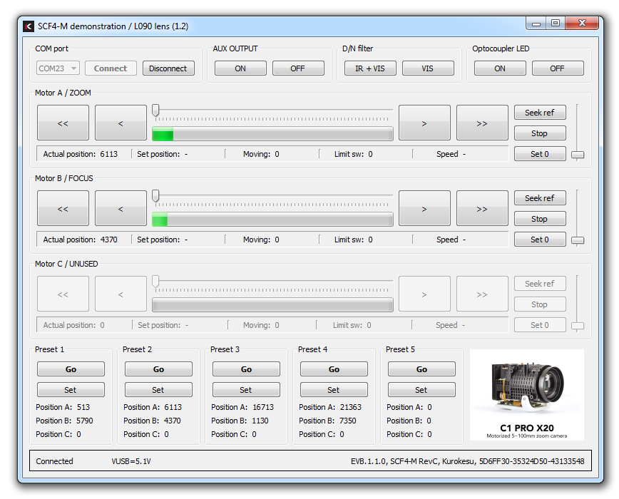](https://wiki.kurokesu.com/uploads/images/gallery/2020-08/5uXscf4-m_gui_demo.png)
Many lenses and motion systems can be connected to the controller and they can be split into two groups - with and without limit/reference switch/sensor. So there are two fundamentally different homing approaches.
1. Homing without limit switch is not very accurate but universal and works with all lenses. Idea is to rotate motor until the mechanical system hits its limit, then rotate a bit backwards and mark position as `0`. The lens should not sustain any irreversible damage, but this procedure should not be performed often.
2. The lens can incorporate various limit or reference switch configurations, therefore homing procedure should be adapted to a particular geometry. For example, the lens has reference opto-interrupter when it crosses the middle of its travel. By reading status register it becomes is clear at which section lens axis is and motor should be moved to center until switch changes status. To complicate things even more optocoupler or any switch has backlash/hysteresis and controller comparator has adjustable lower and upper thresholds. Good understanding of how particular lens behaves is a must and still, it can take a few experiments to set optimal parameters. Some lenses depending on each axis position can have variable travel limits.
Current program version has following homing procedure implemented:
- Move motor by a fixed number of steps (lens may hit mechanical stop)
- Move opposite direction until the switch is actuated
- Move back by a fixed number of steps
- Set current position as 0
Program configuration is saved to `settings.json`. It's a read/write file with the purpose to provide default settings for some parameters like motion speed, jog steps, last used COM port, etc. and save settings and last position when program is closed.
Internal stepper motor driver has 16-bit position counter, absolute positioning is possible within a range of 0..65535 steps, (for 200 steps per revolution motor equals 20 full turns). In relative movement, if motion exceeds 16bit counter range it will overflow and continue the motion. The single move command is also 16 bits.
## Command line
Command-line programs provide quick clean coding templates, examples to understand G-code usage. Programs explain how to:
- Read version string
- Initialize and perform relative movements
- Perform lens homing
- Change motion speed
- Perform an emergency stop
- And more
For the full list see the examples directory
## Terminal
Control commands also can be sent directly from a terminal program of your choice. Baudrate for virtual COM port is irrelevant and communication speed over Full-speed USB 2.0 is 12 Mbit/s.
- Each command must be terminated by a newline
- Each command returns status code or requested information# Drivers
#### Drivers
Stock firmware registers as "STM32 Virtual COM". Most modern operating systems should work out of the box, but original drivers can be downloaded from [STMicroelectronics web page](https://www.st.com/en/development-tools/stsw-stm32102.html)
In some Windows cases Prolific USB to serial controller drivers can claim detected COM port, in this case uninstall driver and install downloaded from ST web page.
# Dedicated boards
Kurokesu SCF4 multi-axis stepper motor controller System On Module (SOM) targets applications where time to market, reliability and small footprint is important. Main control MCU is ST Cortex STM32F103 powerful enough either to run standard or run dedicated standalone firmware. The motor front end is based on ON Semiconductor new and highly specialized driver [LC898201](https://www.onsemi.com/products/power-management/motor-drivers/motor-drivers-stepper/lc898201).
Besides SCF4-M module, some basic boards are offered
#### SCF4-BREAKOUT breakout demo board
**SCF4 BREAKOUT** board allows quick evaluation, testing and prototyping.
##### General view[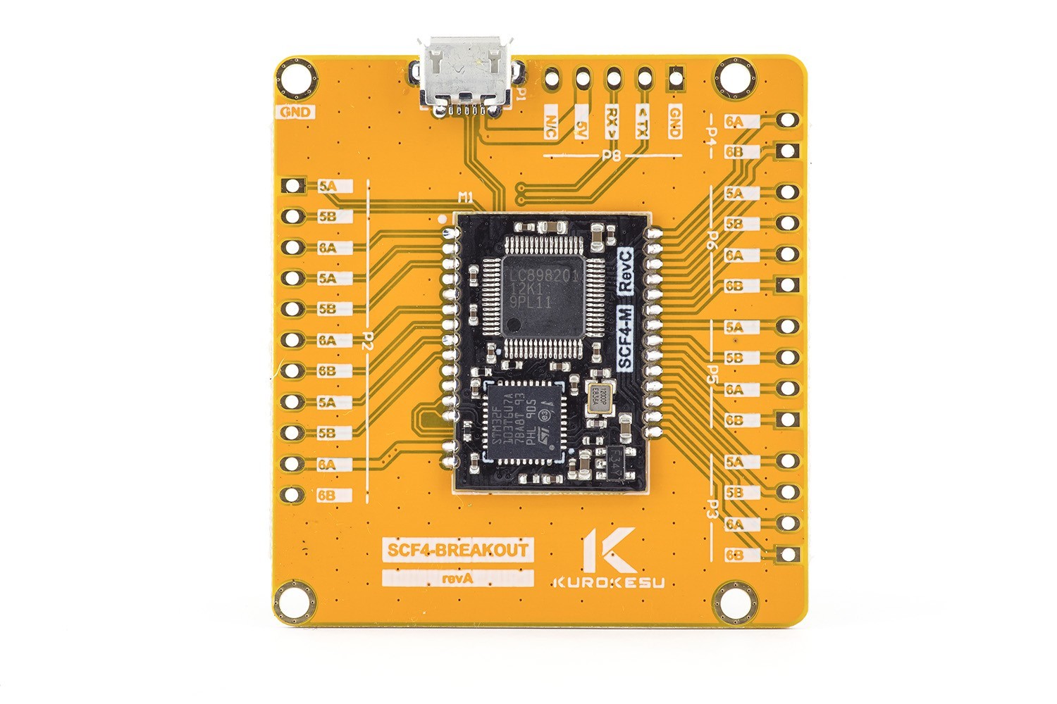](https://wiki.kurokesu.com/uploads/images/gallery/2021-01/Kurokesu-SCF4-breakout-1.jpg)
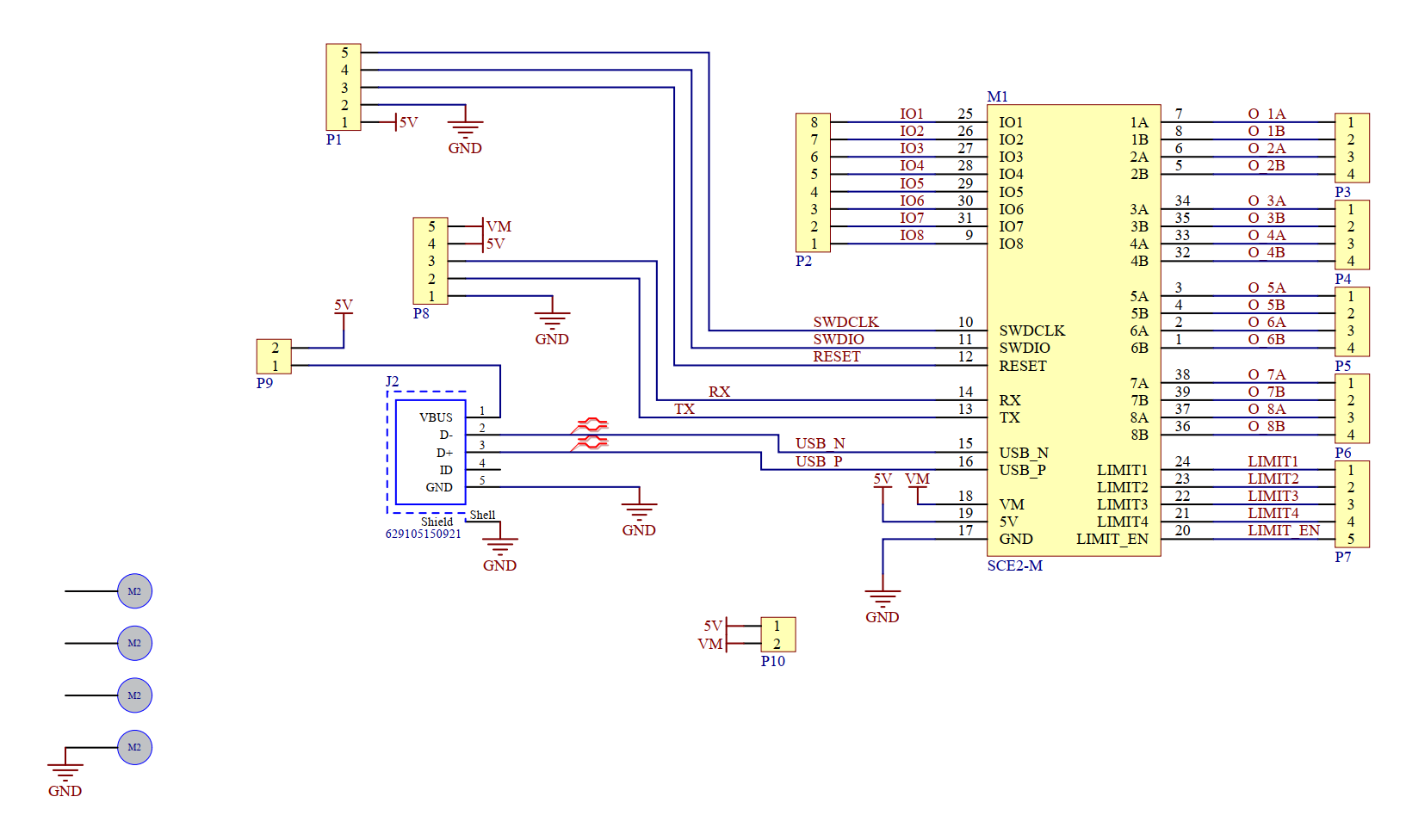
##### Schematics
##### 
##### PCB Layers
[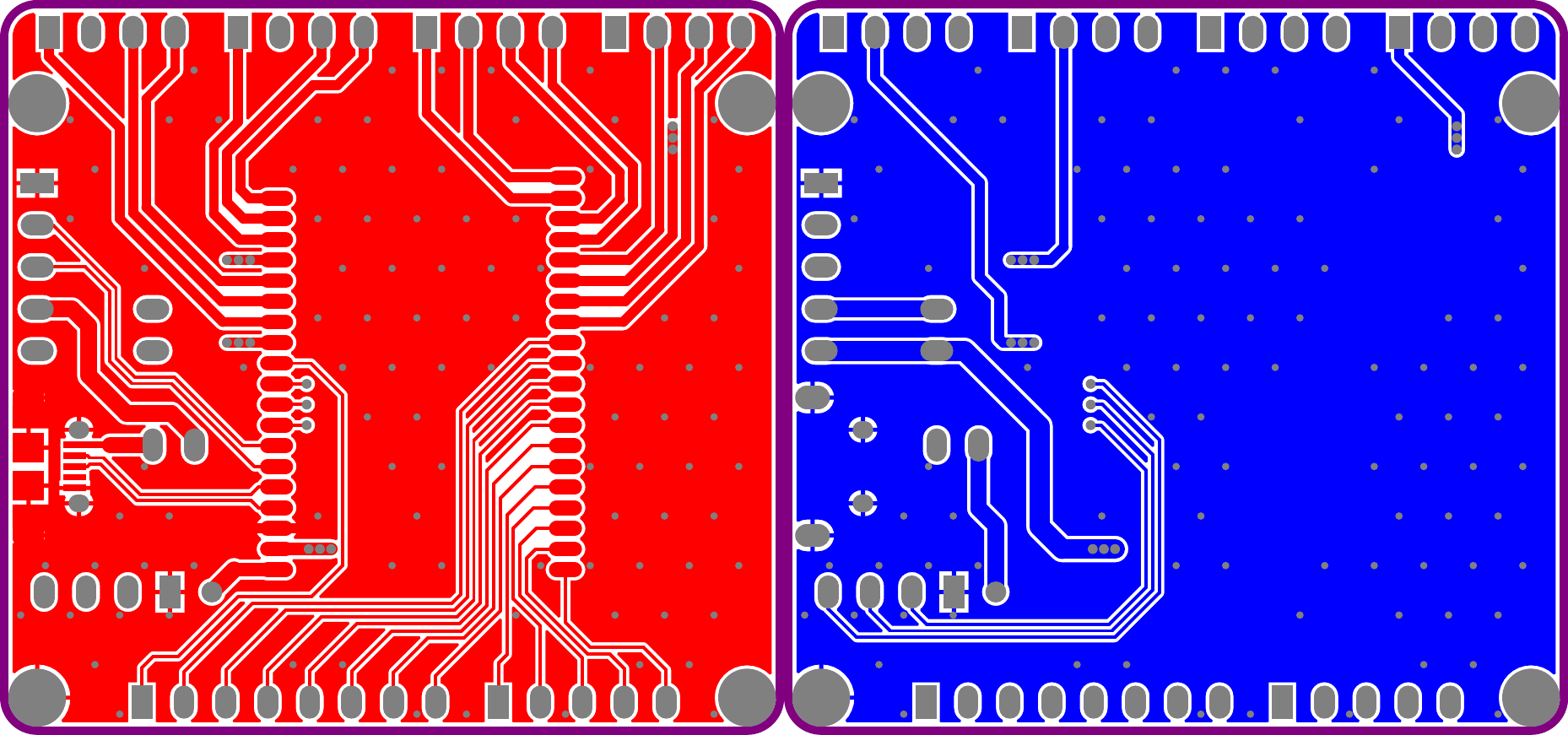](https://wiki.kurokesu.com/uploads/images/gallery/2021-02/layers.png)
#### SCF4-THEIA lens controller board
**SCF4-THEIA** board is designed for THEIA motorized zoom lenses: [TL410P R6](https://www.theiatech.com/tl410-4k-resolution) and [TL1250P R6](https://www.theiatech.com/tl1250-4k-telephoto)
##### General view[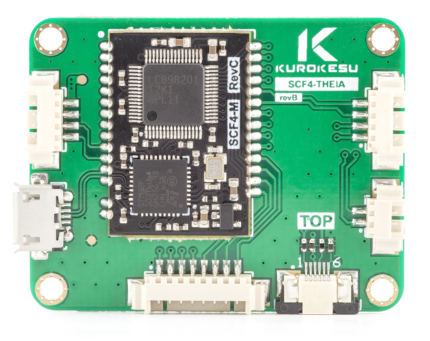](https://wiki.kurokesu.com/uploads/images/gallery/2021-02/IMG_2843_r.jpg)
##### Schematics
[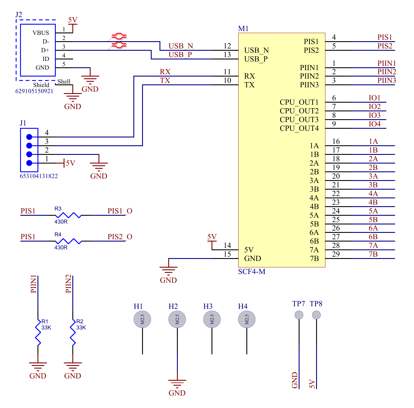](https://wiki.kurokesu.com/uploads/images/gallery/2021-02/SCH_SCE2_THEIA_1of2.png)
[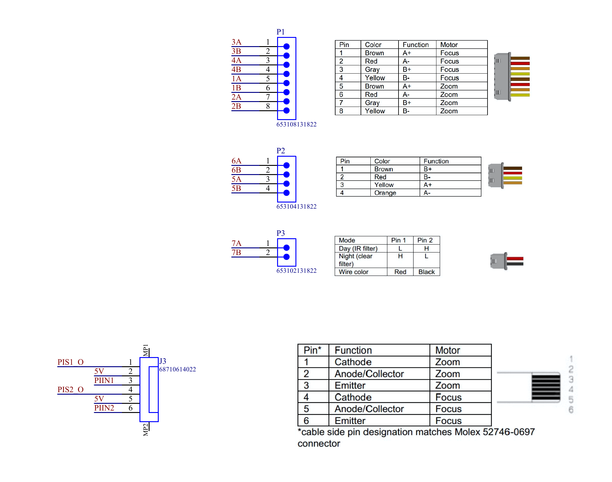](https://wiki.kurokesu.com/uploads/images/gallery/2021-02/SCH_SCE2_THEIA_2of2.png)
##### Typical power profile
[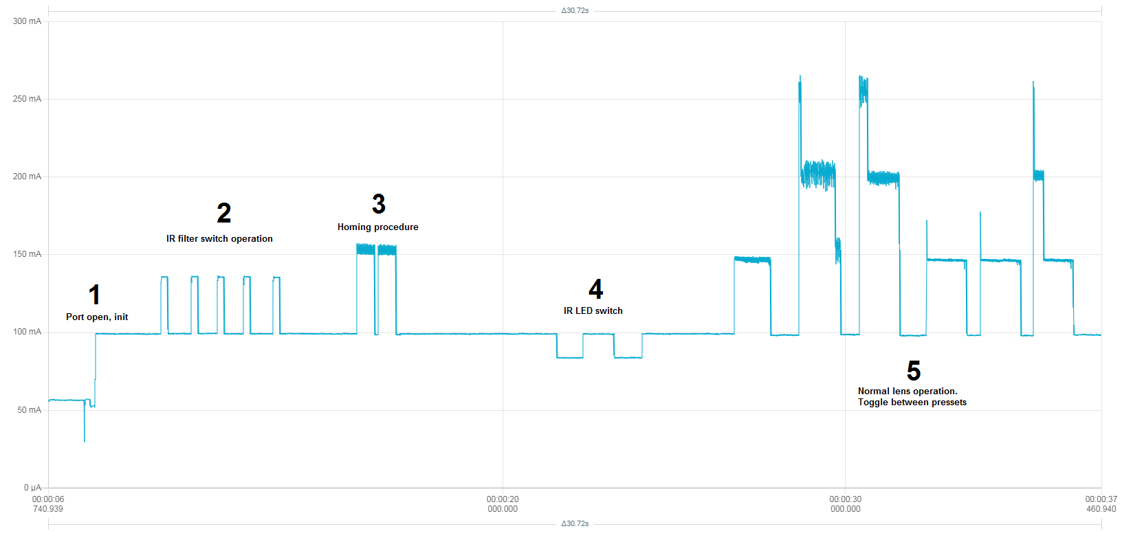](https://wiki.kurokesu.com/uploads/images/gallery/2021-06/scf4_theia_power_profile.png)
##### PCB layers
[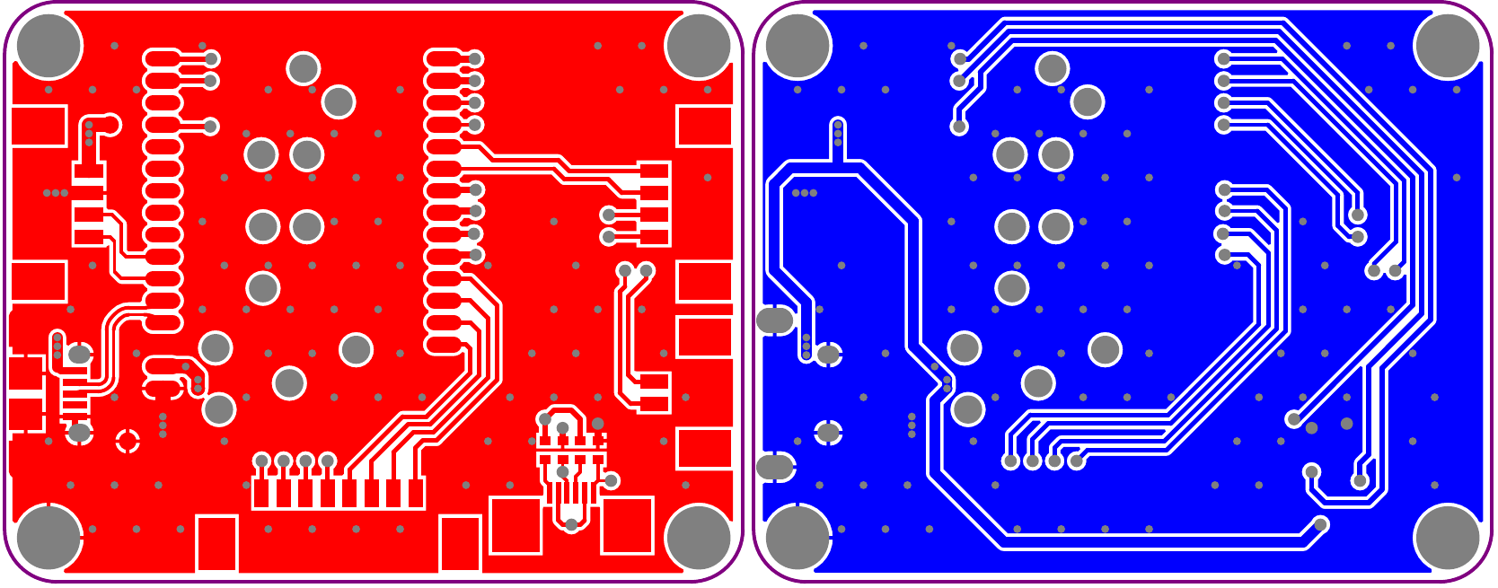](https://wiki.kurokesu.com/uploads/images/gallery/2021-02/LOulayers.png)
#### SCF4-EVB D14 motorized zoom lens controller board
Stepper motor controller evaluation board **SCF4-EVB** is designed to demonstrate **SCF4-M** module capabilities. It can drive two different types of Focus/Zoom/P-Iris lenses. Can be used as a complete product, easily redesigned to drive other lens or fit specific needs.
##### General view
[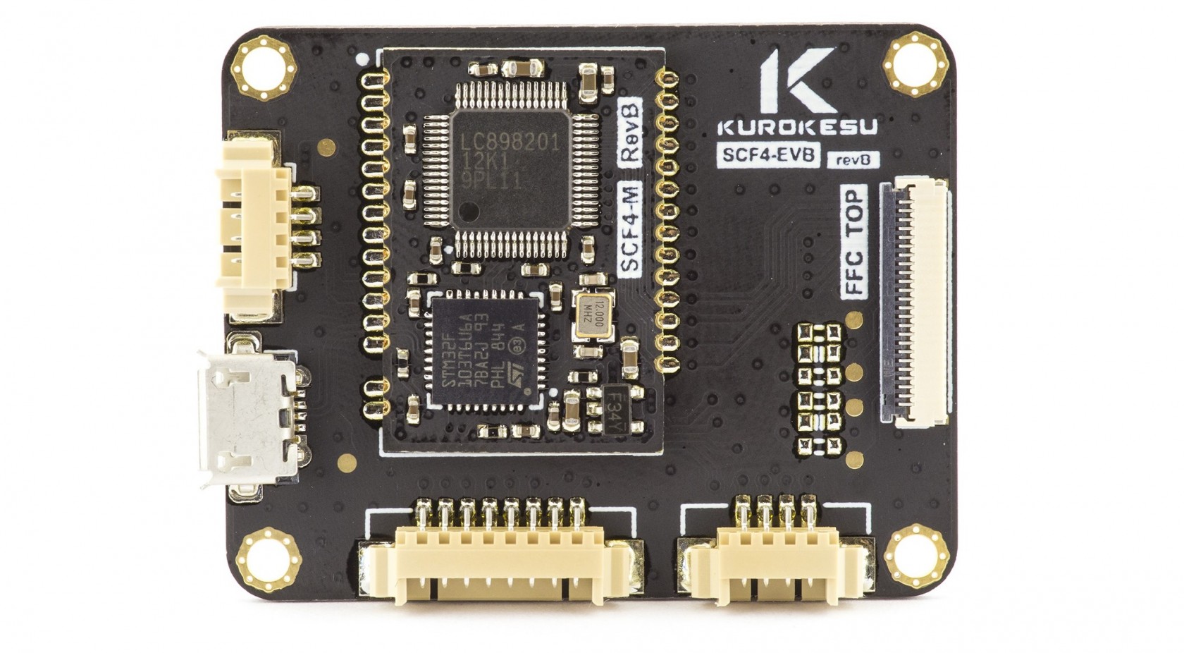](https://wiki.kurokesu.com/uploads/images/gallery/2021-03/scf4-evb.jpg)
##### Schematics
[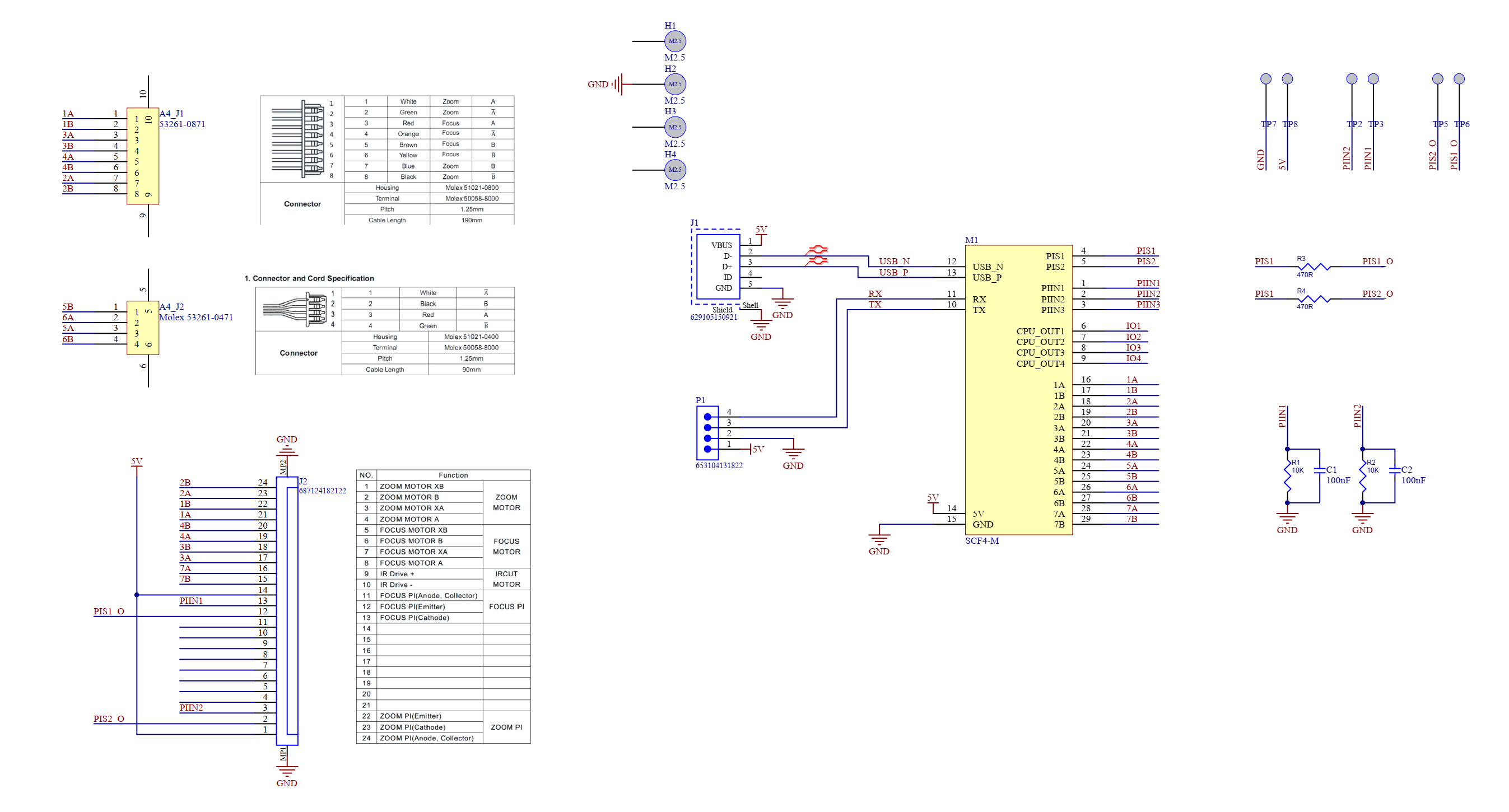](https://wiki.kurokesu.com/uploads/images/gallery/2021-07/SCF4-EVB-sch.png)
##### Features
- Small footprint 42 x 33 x 4.6 mm \[1.65 x 1.3 x 0.18 in\]
- Supports two kinds of lenses
- 3x stepper motor controller with up to 1/1024 micro stepping support for each motor (1/64 set by default)
- 1x H-bridge for coil control (day/night filter switch)
- 2x limit switch processing for precise lens homing/referencing (3x supported by module)
- Direct Full-speed micro USB 2.0
- Optional USART connectivity / GPIO# Precautions and disclaimers
## General disclaimer
- ALL PRODUCTS, PRODUCT SPECIFICATIONS, AND DATA ARE SUBJECT TO CHANGE WITHOUT NOTICE TO IMPROVE RELIABILITY, FUNCTION OR DESIGN OR OTHERWISE
- Kurokesu UAB, its affiliates, agents, and employees, and all persons acting on its or their behalf (collectively, "Kurokesu"), disclaim any and all liability for any errors, inaccuracies or incompleteness contained in any datasheet or any other disclosure relating to any product.
- The Information given herein is believed to be accurate and reliable. However, users should independently evaluate the suitability of and test each product selected for their applications
- See Kurokesu standard terms and conditions for warranty and other information
## Precautions
- Do not short circuit any part of the module
- Do not exceed nominal input
- Do not overload outputs
- Keep the module dry
- Observe the electrostatic discharge (ESD) precautions when handling the product. Damage caused by non-observance of the above instructions is not covered by the warranty
- Power electronics equipped with thermal shutdown circuitry, but if controller becomes too hot disconnect it
- Module is designed exclusively for installation into a device or housing to prevent external influences such as humidity/water or dirt
- Add active and/or passive power filtering circuitry in an electromagnetically noisy environment if a module becomes unstable
- Add active and/or passive power filtering circuitry if module exceeds allowed EMC emissions# Revisions
## Documentation revision history
| **Version** | **Date** | **Changes** |
| 0.1 | 2019-07-01 | Initial documentation created |
| 1.0 | 2019-07-22 | Internal release |
| 1.1 | 2019-07-22 | Disclaimers and precautions added, more complete command description added |
| 1.2 | 2019-07-23 | Minor corrections and mistypes, document public release |
| 1.3 | 2020-07-27 | Migrated to online documentation. Lens section moved to separate document. |
| 1.4 | 2020-08-09 | Added documentation parts affected by EVB.1.1.0 new firmware features, fixed a few typos, minor updates |
| 1.5 | 2020-08-15 | Added I2C documentation |
| 1.6 | 2021-02-07 | Updated some pictures, added more demonstration board details |
## Firmware revision history
| **Version** | **Date** | **Changes** |
| 0.6.52 | 2019-07-01 | - Initial public release version
|
| EVB.1.0.0 | 2019-07-14 | - Bump to 1.0.0 release
- Consolidated version reporting into single string
- Code cleanup
|
| EVB.1.0.1 | 2019-07-14 | - Minor bug fixes
|
| EVB.1.0.2 | 2019-07-18 | - Added new advanced commands: M241..M244
- Fixed: set motor idle power to 0 is not allowed
- Fixed: default relative movement mode after reset
|
| EVB.1.1.0 | 2020-05-30 | - Added USART support over 4 pin connector besides original USB-CDC mode
|
| EVB.1.2.0 | 2020-08-15 | - Added I2C support (forked from EVB.1.1.0)
|
| EVB.1.3.0 | 2020-08-09 | - Added power input voltage ADC readout command
- Added AUX output on/off control commands
|