
L086-DEVKIT
Brief
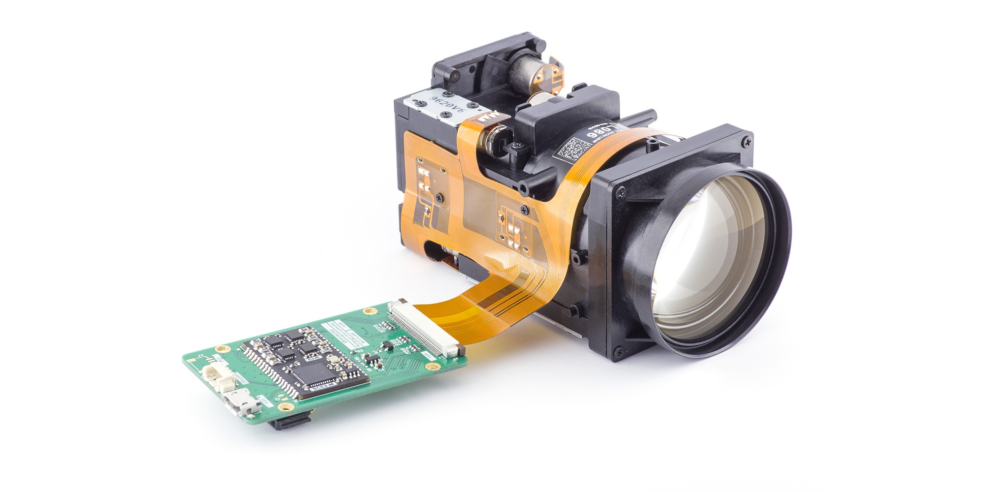
L086 is 6.8-120mm focal length (18x) motorized zoom lens is designed for 1/1.8" image sensors, has zoom/focus/iris functions, designed for 8M sensors.
Specifications
Optics
| Image sensor | 1/1.8" Effective image area > 9.2mm |
| Focal distance | 6.8 ~ 120mm / ±5% |
| Aperture | f/1.6 ~ f/4.1 |
| Focus range |
|
|
Field of view (D=8.81mm) |
|
|
Distortion |
|
|
Recommended image sensor |
IMX334 |
Mechanics
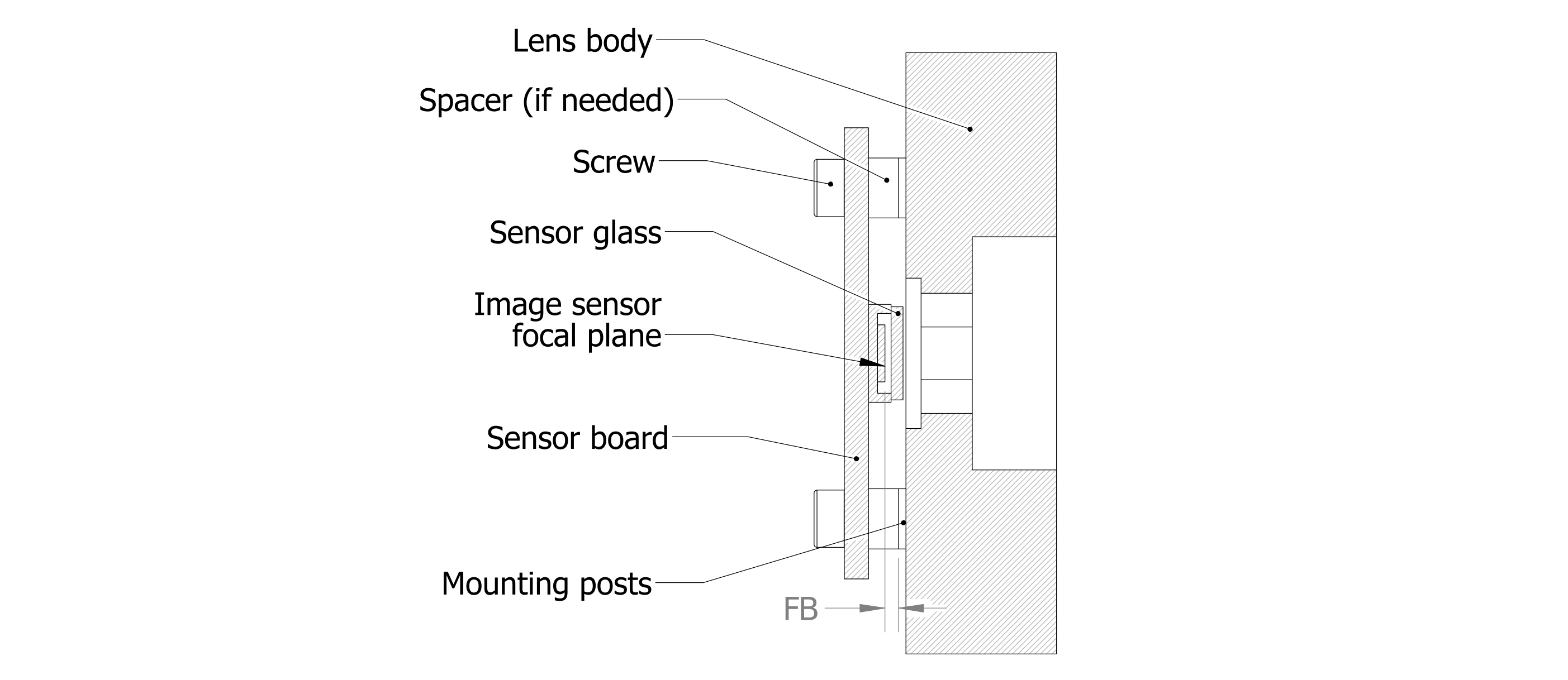
| Flange back (FB, see diagram below) |
+0.374 (in glass t=0.3 IRCF) |
| Lens zoom structure | The stepper motor is directly connected to the screw |
| Lens focusing structure | The stepper motor is directly connected to the screw |
| Lens size |
|
| Weight | 138g (+controller 7.8g) |
In order to accommodate different image sensors, the focal distance is set back by flange back (FB) distance. The actual distance for a specific sensor has to be calculated and spacers used. If the image plane is not set correctly, focus irregularities in the projected picture are expected.
Motor specifications
| Screw pitch | 0.4mm |
| Spiral rotation direction | Right |
| Rated voltage | 5.0 VDC |
| Coil resistance | 60Ω ± 10% / phase (T=25°C) |
| Phase count | 2 |
| Step angle | 18° / step |
| Max start frequency | 800 PPS @ at 5.0 VDC |
| Max operating frequency | 1200 PPS @ 5.0 VDC |
| Pull torque | 2.8 gf-cm min (at 480 PPS @ 5.0 VDC) |
|
Push torque |
3.8 gf-cm min (at 480 PPS @ 5.0 VDC) |
| Operating temperature range | -30°C ~ +70°C |
Position alignment sensor PI
| Model number | RPI-222 / ROHM |
Iris
| Driving resistance | 120Ω ± 10% (T=20°C, 65% RH) |
| Braking resistance | 120Ω ± 10% (T=20°C, 65% RH) |
| Close to open operation | 3.5 ~ 5.0V |
| Open to close operation | 0 ~ 0.8V |
IR switch
| Coil resistance | 22.5 ± 10% (T=20°C) |
| Operation voltage |
4.5 ~ 5.0V |
| Current consumption |
144 ~ 200mA |
| Filter thickness |
0.3mm |
| Switching time |
200 ~ 500ms |
| Filters |
|
Zoom-Focus curve diagram

Please check the software in the GitHub repository for more detailed table.
Wiring
Lens signals routed by 43 pin 0.5mm pitch FFC cable. Contacts facing top.

| Nr | Function |
| 1 | ZOOM1 MOTOR B- |
| 2 | ZOOM1 MOTOR A+ |
| 3 | ZOOM1 MOTOR B+ |
| 4 | ZOOM1 MOTOR A- |
| 5 | ZOOM2 MOTOR B- |
| 6 | ZOOM2 MOTOR A+ |
| 7 | ZOOM2 MOTOR B+ |
| 8 | ZOOM2 MOTOR A- |
| 9 | ZOOM1 PI(ANODE) |
| 10 | ZOOM1 PI(CATHODE EMITTER) |
| 11 | ZOOM1 PI(COLLECTOR) |
| 12 | GND |
| 13 | IRIS DRIVE+ |
| 14 | GND |
| 15 | IRIS HALL- |
| 16 | IRIS BIAS- |
| 17 | IRIS HALL+ |
| 18 | IRIS BIAS+ |
| 19 | GND |
| 20 | IRIS DRIVE- |
| 21 | IRIS CONT- |
| 22 | IRIS CONT+ |
| 23 | IR- |
| 24 | IR+ |
| 25 | FOCUS PI(CATHODE EMITTER) |
| 26 | FOCUS PI(COLLECTOR) |
| 27 | FOCUS PI(ANODE) |
| 28 | ZOOM2 PI(CATHODE EMITTER) |
| 29 | ZOOM2 PI(COLLECTOR) |
| 30 | ZOOM2 PI(ANODE) |
| 31 | TEMP COM |
| 32 | TEMP OUT |
| 33 | FOCUS MOTOR B- |
| 34 | FOCUS MOTOR A+ |
| 35 | FOCUS MOTOR B+ |
| 36 | FOCUS MOTOR A |
Dimensions
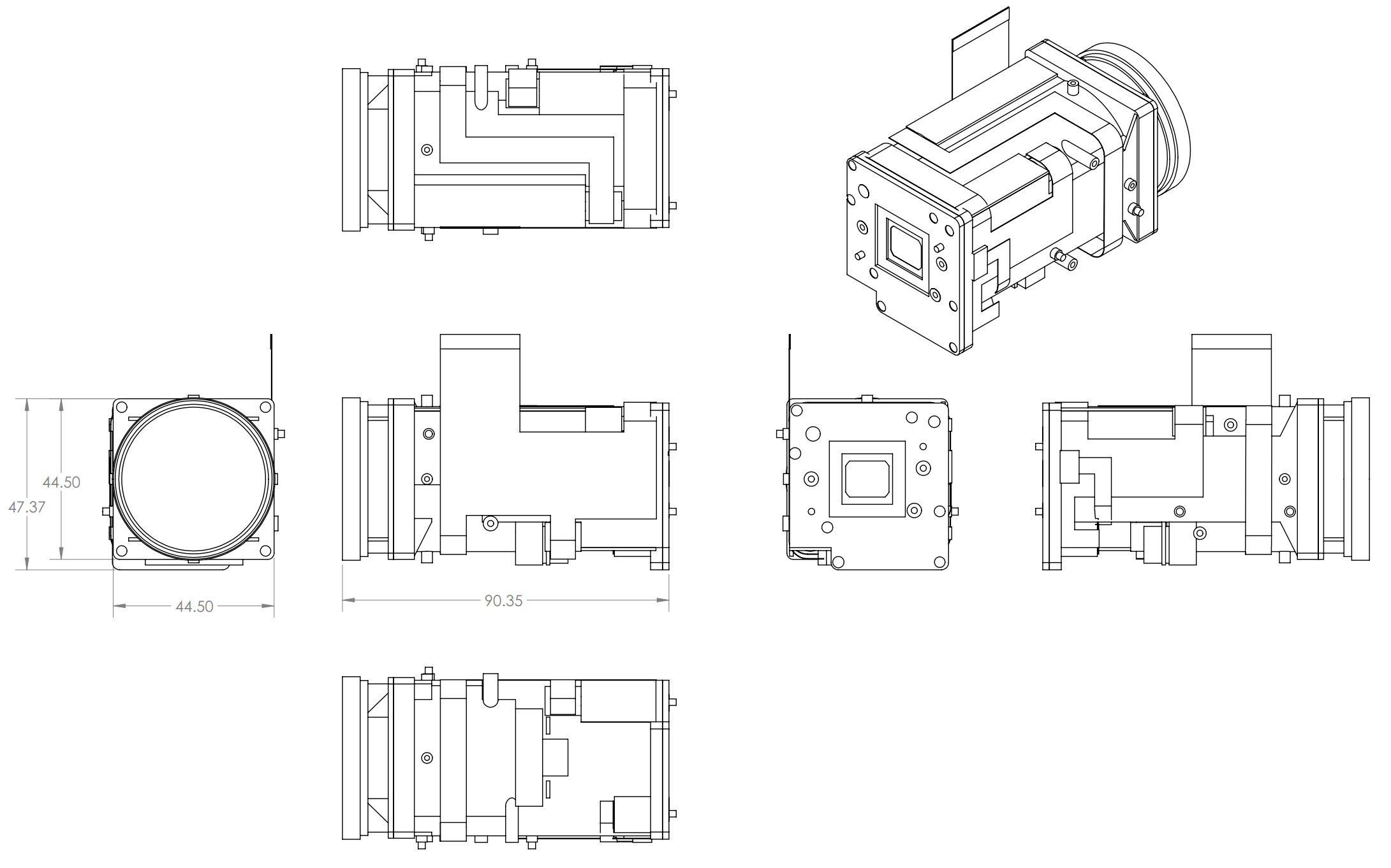
Detailed 3D model is hosted on GitHub 3D models repository
Controller SCE2-L086
SCE2-L086 is inexpensive dual layer application board designed to match lens FFC routing and topology based on SCE2-M 4 channel stepper motor controller module. Controller is based on STM32 microprocessor and TMC2300 motor drivers. Modern stepper motor drivers allow wide range of operation and suitable from operating NEMA17 to micro motor. Control logic is based on CNC control firmware GRBL.

PCB revisions
RevA
- Initial lens tests
- Simplified DC iris control (on/off)
- For testing use 44pin FFC
- Check IR filter control with trinamic
- Check actual homing, fine tune GRBP parameters
- Check if FFC connector numbering matches cable
- Add I2C thermometer
RevB
- Refine design
- Use new 43 pin FFC connector
- Replace internal I2C thermometer with slave connector
- Use NTC with on-board ADC for temperature reading
RevC
- Replaced 43 pin FFC connector to 36 pin
- Updated some resistor values
Features
- USB and 3.3V UART control
- 4 axis motion controller
- Fully integrated design
- Powered by USB 5V rail
- I2C slave for external sensors and controllers (Functionality is determined by firmware)
- Linear path interpolation
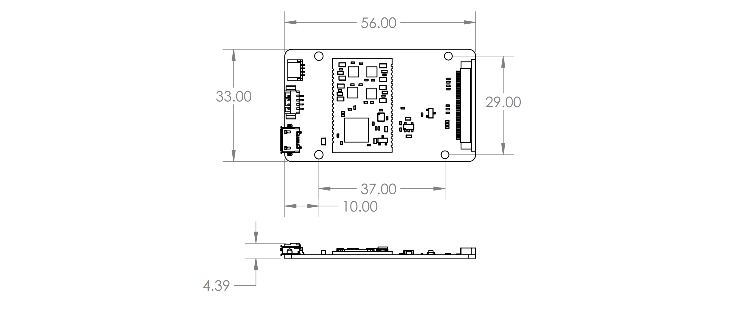
Dimensions
Power profile
Typical power consumption of the lens
