
Reading and writing TMC2300 registers
Firmware has implemented functionality to read and write individual Trinamic TMC2300 registers over internal UART single wire interface. It shares transmit and receive line like an RS485 based interface. Data transmission is secured using a cyclic redundancy check and each TMC2300 driver is addressed individually as follows:
| Axis | Address |
| X | 0 |
| Y | 1 |
| Z | 2 |
| A | 3 |
| Broadcast to all axes | 9 |
Official TMC2300 documentation
All numbers in g-code arguments are decimal base numbers
Write registers
Write register command forwards g-command arguments to TMC2300 configuration interface. While it is not recommended because of stability issues, write command can be sent even if motors are turning (G0, G1, ... commands)
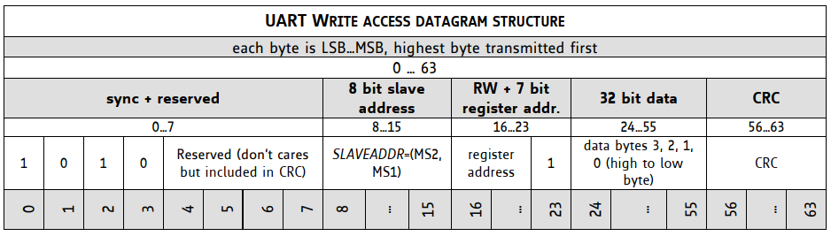
7'th bit of TMC2300 register has to be set to 1, thus for example 0x10 IHOLD_IRUN becomes 0x90
| G100 | P<xx> | L<xx> | N<xx> | S<xx> | F<xx> | R<xx> |
| G-command | TMC2300 address | TMC2300 register (mask with 0x80) | DATA3 | DATA2 | DATA1 | DATA0 |
Required checksum is calculated in firmware
Read registers
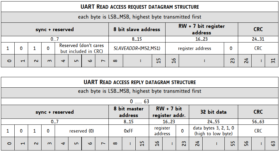
Read registers command has two arguments TMC2300 address and register address. It responds to terminal immediately.
| G101 | P<xx> | R<xx> |
| G-command | TMC2300 address | TMC2300 register |
Response is decimal coded 12 bytes. Sample reply looks like this: [TMC:5,0,16,112,5,255,16,0,0,0,0,157]
| Reply byte | Meaning |
| 0 | Echo transmit byte0 |
| 1 | Echo transmit byte0 |
| 2 | Echo transmit byte0 |
| 3 | Echo transmit byte0 |
| 4 | Reply from TMC2300 sync (0x05) |
| 5 | Address |
| 6 | Register |
| 7 | Data byte3 |
| 8 | Data byte2 |
| 9 | Data byte1 |
| 10 | Data byte0 |
| 11 | Checksum |
Examples
Set motor X current
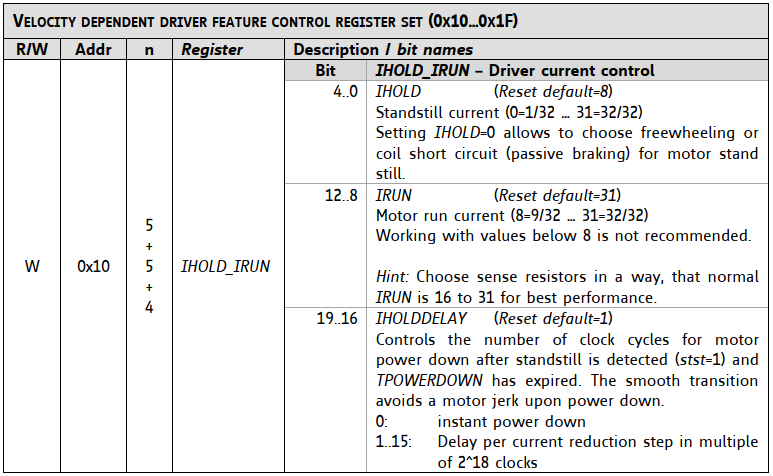
Each motor driver can drive different motor. Power and other settings can be set individually. For example IHOLD_IRUN (0x10) register controls motor idle, run and timing parameters.
G100 P0 L144 N0 S0 F10 R5
| G100 | Write to TMC2300 g-command |
| P0 |
Driver address = 0 (X axis) |
| L144 |
TMC2300 register IHOLD_IRUN (0x10) 0x10 ->(set 7'th bit to 1)-> 0x90 = 144 (dec) |
| N0 | Data3 = 0 (not used) |
| S0 | Data2 = 0 (see IHOLDDELAY in table below) |
|
F10 |
Data1 = 10 (see IRUN in table below) |
| R5 | Data0 = 5 (see IHOLD in table below) |
Read input register
Each TMC2300 driver has input status registers GSTAT (0x01) indicating over temperature, short circuit, and more.
G101 P0 R1
Response looks like:
[TMC:5,0,1,193,5,255,1,0,0,0,1,154]
Response contains only 3 bits of useful information. See explanation in table below.
