Pinout
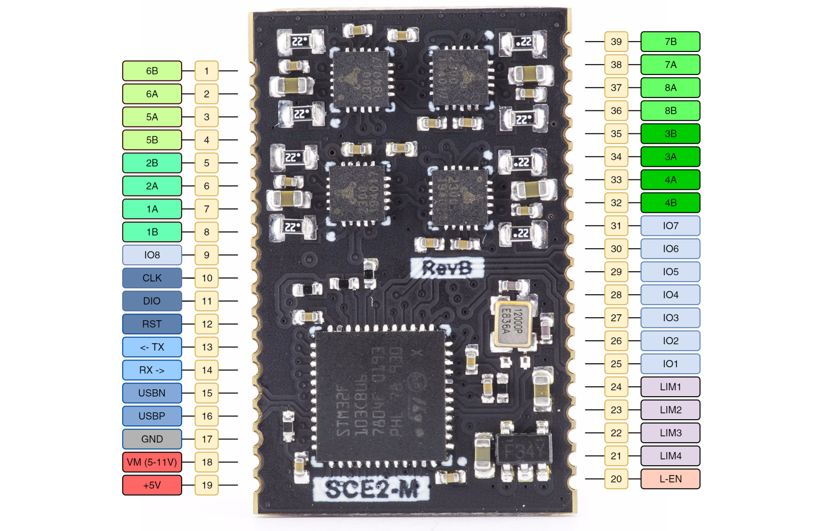
SCE2-M module has some STM32 pins routed to external pads. Pads grouped by functionality provided in tables below.
Pinout
GPIO pin mapping table
| IO pin | CPU port | Function | CPU features |
| 1 | PB1 | SPINDLE ENABLE | ADC |
| 2 | PB9 | PROBE | I2C SDA |
| 3 | PA8 | PWM OUTPUT | |
| 4 | PB4 | FLOOD | |
| 5 | PB3 | MIST | |
| 6 | PB0 | SPINDLE DIR | ADC |
| 7 | PB5 | STOP | |
| 8 | PB8 | I2C SCL |
PA8 (PWM OUTPUT) is set to 10kHz frequency, but can be adjusted in firmware.
Limit switch mapping table
| Port | Net name |
| PB12 | LIMIT1 |
| PB13 | LIMIT2 |
| PB14 | LIMIT3 |
| PB15 | LIMIT4 |
| PA9 | LIMIT_EN |
UART pin mapping table
| CPU port | Net name |
| PB7 | USART1_RX |
| PB6 | USART1_TX |
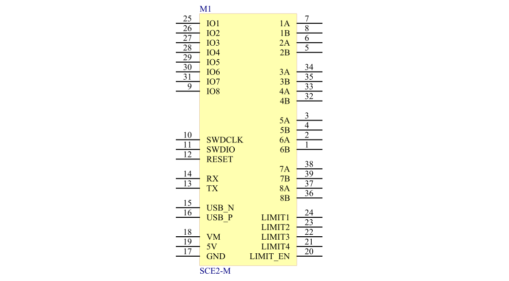
Schematic symbol
5V is used for motor drivers. Logic level of all GPIO pins is 3.3V


